weikertball said:higher compression means a larger throat, correct?
No, smaller.
GM
Re: Re: Request for more info about your measurement
Hi Ian,
I think you missed my point (I agree with everything you say, but remain very puzzled by the claim of correct frequency response but incorrect excursion).
The excursion is given by the force from the motor (simple, surely right); driving the cone which must be represented just as well as in a reflex, say; into an impedance that depends on a bunch of things including the resonances of the pipe and addition of rear and front waves. So it must be the impedance that is wrong. But I don't yet see how there can be an error that only shows up in the TH case yet makes the excursion incorrect at all frequencies. (Particularly as the same impedance must be right in most respect to be useful to predict the radiation.)
If the excursion is wrong only in a particular band (and that could be the most important one that everyone concentrates on when measuring), I could much more easily see how some feature that is not included in the model makes a big difference.
Ken
iand said:
You're right about the varying load and mix of front/rear radiation with increasing frequency -- this is how the tapped horn works, and is precisely what is modelled with Hornresp and Akabak.
There's no inherent reason why the simulations should be wrong because of this, the analysis methods used (which just solve well-known electroacoustic equations) should be perfectly capable of analysing much more complex systems than a tapped horn.
From what's been reported (by Tom, William and others) there doesn't seem to be a significant discrepancy in simulated vs. measured frequency response (flatness/rolloff), the discrepancy (if there is one) is in excursion (lower) and efficiency (higher).
Ian
Hi Ian,
I think you missed my point (I agree with everything you say, but remain very puzzled by the claim of correct frequency response but incorrect excursion).
The excursion is given by the force from the motor (simple, surely right); driving the cone which must be represented just as well as in a reflex, say; into an impedance that depends on a bunch of things including the resonances of the pipe and addition of rear and front waves. So it must be the impedance that is wrong. But I don't yet see how there can be an error that only shows up in the TH case yet makes the excursion incorrect at all frequencies. (Particularly as the same impedance must be right in most respect to be useful to predict the radiation.)
If the excursion is wrong only in a particular band (and that could be the most important one that everyone concentrates on when measuring), I could much more easily see how some feature that is not included in the model makes a big difference.
Ken
Hi KSTRAIN,
HornResp predicted max deflection at 40, so I used a 40 Hz sine wave. I don't have the capability or the property (acres & acres) necessary to do real analysis. I posted my HornResp data at 1327.
While I have used a 'scope and I have a cheap multimeter and a Rat Shack SPL meter, my academic efforts have been more along the mechanical line. I'd like to have a better understanding of Tapped Horns. Is TrueRTA the way to go? What other gear would be required for a minimum tapped horn lab (measurement microphone, multimeter w/ true VRMS, etc)?
Since you already have the Rat Shack meter,a 1/3 octave pink noise CD would get you started for about $15.00.Available on Ebay
The FAQ section at Trueaudio.com has the info on what you need to use the TrueRTA program.There is also a link to the AVS Science Forum thread"TrueRTA for Dummies" that gives more info.
I'm in the process of setting up TrueRTA on my computer,now I need to make a roll-around desk so I can move it out to the living room to use it.(or just get a laptop...)
Don Snyder said:Hi KSTRAIN,
HornResp predicted max deflection at 40, so I used a 40 Hz sine wave. I don't have the capability or the property (acres & acres) necessary to do real analysis. I posted my HornResp data at 1327.
Hi Don,
many thanks. I put your model in Hornresp and had a look. Did you check if 40 Hz really was the maximum (displacement)? The slope of the displacement vs. frequency curve is quite steep just below the maximum. If a parameter such as the effective length of the horn is a little bit off , the response at 40Hz could be as expected (or even enhanced a bit) but with a smaller displacement.
With folds and all I certainly found it hard to be sure how to set the lengths to within several inches of the model.
As regards measuring equipment, I should probably not comment until I've managed to make my own measurements, but a calibrated ECM8000, soundcard, various software (scopes, analysers, mostly free), a few resistors and a multimeter are all I planned to use (that does not allow for measuring displacement). I'd really like to bring a laser vibrometer from the lab to home, but that is not much easier than taking the horn to work (i.e. impractical).
I thought of building a model TH to test, but have generated more than enough sawdust recently. A compromise would be to stick a flag on the back of the cone like you suggested and use a LED/photodiode shadow sensor - they can be quite linear (from a few <1nm to ~1mm rms), and easy to calibrate with a micrometer.
Ken
kstrain said:
Hi Don,
many thanks. I put your model in Hornresp and had a look. Did you check if 40 Hz really was the maximum (displacement)? The slope of the displacement vs. frequency curve is quite steep just below the maximum. If a parameter such as the effective length of the horn is a little bit off , the response at 40Hz could be as expected (or even enhanced a bit) but with a smaller displacement.
With folds and all I certainly found it hard to be sure how to set the lengths to within several inches of the model.
As regards measuring equipment, I should probably not comment until I've managed to make my own measurements, but a calibrated ECM8000, soundcard, various software (scopes, analysers, mostly free), a few resistors and a multimeter are all I planned to use (that does not allow for measuring displacement). I'd really like to bring a laser vibrometer from the lab to home, but that is not much easier than taking the horn to work (i.e. impractical).
I thought of building a model TH to test, but have generated more than enough sawdust recently. A compromise would be to stick a flag on the back of the cone like you suggested and use a LED/photodiode shadow sensor - they can be quite linear (from a few <1nm to ~1mm rms), and easy to calibrate with a micrometer.
Ken
Hi Ken
A simple way to measure the cone displacement is to use one of those vernier caliper/depth gauge gadgets where the depth is measured using a metal rod which sticks out of the end -- cheap plastic ones are only a few pounds, or sometimes free as promotional freebies.
Fasten this to the driver frame with more clearance than the expected maximum excursion, measure the position of the cone with no signal, then pull the slider back, apply signal, and push gently back in until it just touches the vibrating cone at peak travel.
Admittedly this only measures travel in one direction, but assuming the excursion is reasonably symmetrical you can easily measure to 0.1mm accuracy this way.
Since we're only really worried about maximum excursion, it's easy to sweep the frequency up and down by a few Hz to find where this occurs.
Cheers
Ian
If you don't want to buy a CD go on over to Home Theater Shack and download Room EQ Wizard. http://www.hometheatershack.com/roomeq/
It will do many things that you want done, and it's free.
If I were to dig up the specs on a couple of 10" round Sony xplod drivers that I have laying about would someone here be willing to plug them into hornresp, or akabak to see how they would model in a tapped horn?
Paul
It will do many things that you want done, and it's free.
If I were to dig up the specs on a couple of 10" round Sony xplod drivers that I have laying about would someone here be willing to plug them into hornresp, or akabak to see how they would model in a tapped horn?
Paul
thanks tb46
i can now see how the different parts relate to the atual horn, i find if i change s4 from 1050 to 500, this gives me a desired response
this was from modifying the input perimeters you used, i am guessing from the huge difference it makes that the inductance is under the LE tab, what value of inductor do i need,
im guessing that if the driver le is 1.48 and the imput in horn resp is 7.40, that i need a inductor with a value of 5.92, if thats how there measured, seems simple, do these act as low pass filters as well? i heard that somewhere.
so im thinking if i basically make the mouth half the size i will get this response with your diagram, which is a tiny bit different, but pretty much the same as mine. am i correct?
i can now see how the different parts relate to the atual horn, i find if i change s4 from 1050 to 500, this gives me a desired response
this was from modifying the input perimeters you used, i am guessing from the huge difference it makes that the inductance is under the LE tab, what value of inductor do i need,
im guessing that if the driver le is 1.48 and the imput in horn resp is 7.40, that i need a inductor with a value of 5.92, if thats how there measured, seems simple, do these act as low pass filters as well? i heard that somewhere.
An externally hosted image should be here but it was not working when we last tested it.
so im thinking if i basically make the mouth half the size i will get this response with your diagram, which is a tiny bit different, but pretty much the same as mine. am i correct?
Hi Naudio:
When you use a series inductor you should add the inductors ohmic resistance under Rg (e.g.: 0.25 Ohm). The exact value of the inductance does not seem to be too critical, give or take a half a mH. Yes, they do have their normal first order filter action.
I do not know if the reverse taper that you are applying between S3 and S4 is correctly modeled in Hornresp, generally I would advice against choking the horn that much, often you get a better response by increasing the flare from S3 to S4 over the average horn flare. Try entering it into the newest Hornresp V18.30, it has four active horn sections and the new Tapped Horn Wizard (just be aware that V18.30 does not do tapped horns with only three sections.)
How to fold-up a Tapped Horn
Figure 1: The horn is cut into four equal length sections.
Figure 2: The sections are stacked, and some boards are added to represent the additional area of the edges of the flare panels. For our first attempt, consider the edges of fig. 2 as the inside outline of our horn.
Figure 3, 90 degree turns: Let AB be the desired mouth dimension, and set the slope of BC to match the slope of fig. 1. Next, arc DE is drawn using C as the pivot point and EF is constructed perpendicular to BC. Similarly, arc GH is drawn using F as the pivot point and a line is constructed from H perpendicular to EF.
Figure 4, 180 degree turns: To continue, we must consider the thickness of the flare panels. Add lines one material thickness above BE, to the left of EH, and below HL to show the other edge of those flare panels. To find point I, Construct the centerline of panel HL. Next, the arc JK is drawn using I as the pivot point, which establishes the length of panel HL and the point K.
Next, we construct panel KP. Draw a horizontal line from K to P and a parallel line a material thickness below it. To find point M, construct the centerline of panel KP. Next, arc NO is drawn using M as the pivot point, which establishes the length of panel KP and the point O. Complete the horn by extending the lower line of flare KP and a line from point O until they are separated by the throat height, T.
There are two corrections that we will need to make, one to the area of our box, and the second to the width. There are two gray areas, the right one is the area of the box that didn’t get used. The left one is the part of the horn that didn’t make it into the box. If the left one is larger than the right, increase the box area by the difference, else decrease the box area.
Last, measure the length of the horn that didn’t make it into the box, and divide by 3. That is the needed increase in width. From the new area and the new width, calculate the new height. Now, try again!
Attachments
Tapped horns vs front loaded horns
Another thing, would there be any difference in performance between front loaded and tapped below the frequency where the horn unloads?
Right now I'm torn between building a front loaded and tapped...
Just a quick question, are there any disadvantages with going for a tapped horn instead of a front loaded horn enclosure? I know the front loaded will be larger than the tapped but front loaded also tends to have very little or no harmonic distortion which is nice. Do tapped horns do this also?dwk123 said:judtoff - William is spot on. For a given size, a tapped horn will outperform a Tuba if we're only worried about use as a sub. The 'problem' with Bills Tubas is that they're wider band devices, and the sub frequencies are at the lower-efficiency end of their passband. For example, the Table Tuba holds ~95dB efficiency down to 30 Hz, but needs 9 cu ft. My models show a tapped horn holding 95dB down to 25Hz in about half that size.
Another thing, would there be any difference in performance between front loaded and tapped below the frequency where the horn unloads?
Right now I'm torn between building a front loaded and tapped...
Re: Tapped horns vs front loaded horns
Tapped horns have the same distortion as a front-loaded horn with the same excursion -- which means better than a small front-loaded horn (loading is poor) but not as good as a huge one (excursion peaks are larger). Tapped horn distortion can be worse if a harmonic hits one of the out-of-band resonant peaks which can amplify it by 10dB or so (see below).
Below where the horn unloads you've only got the stiffness of the driver suspension (no rear chamber), so it won't take much to bottom the driver unless you use a driver optimised for a tapped horn which has higher Fs -- the ideal total compliance is the same as a front-loaded horn driver with sealed rear chamber, which typically means Fs<Fhorn for a normal horn and Fs>Fhorn for a tapped horn.
I'd say that the only significant disadvantage is the big high-Q peaks just above the passband, which don't get attenuated enough even with a 24dB/octave crossover and can amplify harmonic distortion.
To remove these you need either a *very* fast rolloff crossover (which means almost certainly digital), or to null out the peaks with quarter-wave resonator pipes like in the DTS-20 (which need tweaking and damping), or notch them out electronically using a parametric equaliser.
Of course a front-loaded horn with similar cutoff and ripple is much *much* bigger, it's not really a fair contest")
Ian
MikeHunt79 said:
Just a quick question, are there any disadvantages with going for a tapped horn instead of a front loaded horn enclosure? I know the front loaded will be larger than the tapped but front loaded also tends to have very little or no harmonic distortion which is nice. Do tapped horns do this also?
Another thing, would there be any difference in performance between front loaded and tapped below the frequency where the horn unloads?
Right now I'm torn between building a front loaded and tapped...
Tapped horns have the same distortion as a front-loaded horn with the same excursion -- which means better than a small front-loaded horn (loading is poor) but not as good as a huge one (excursion peaks are larger). Tapped horn distortion can be worse if a harmonic hits one of the out-of-band resonant peaks which can amplify it by 10dB or so (see below).
Below where the horn unloads you've only got the stiffness of the driver suspension (no rear chamber), so it won't take much to bottom the driver unless you use a driver optimised for a tapped horn which has higher Fs -- the ideal total compliance is the same as a front-loaded horn driver with sealed rear chamber, which typically means Fs<Fhorn for a normal horn and Fs>Fhorn for a tapped horn.
I'd say that the only significant disadvantage is the big high-Q peaks just above the passband, which don't get attenuated enough even with a 24dB/octave crossover and can amplify harmonic distortion.
To remove these you need either a *very* fast rolloff crossover (which means almost certainly digital), or to null out the peaks with quarter-wave resonator pipes like in the DTS-20 (which need tweaking and damping), or notch them out electronically using a parametric equaliser.
Of course a front-loaded horn with similar cutoff and ripple is much *much* bigger, it's not really a fair contest
Ian
Re: Re: Tapped horns vs front loaded horns
A couple more advantages:
- It's generally agreed that a tapped horn "tolerates" a driver with a higher FS. If you have two drivers of equivalent parameters, the one with the higher FS will have a higher sensitivity. This is often overlooked, and can add an additional DB or two to the overall output. One trend I've noticed in sealed box subwoofers is to use drivers with an FS in the teens. A driver like that almost invariably has a sensitivity in the low 80s. The tapped horns we've seen in this thread are sometimes using drivers with sensitivity ratings in the high 90s. That fact alone can contribute FIFTEEN db to the base efficiency of a tapped horn vs a sealed sub.
- It's damn near impossible to get a front loaded horn to go down to 15 or 20hz. Even the vaunted Lab Horn rolls off well before that. If you want to get bass at 20hz or lower, you're basically limited to bandpass, sealed, vented, tapped horn, transmission line and acoustic lever.
iand said:
Tapped horns have the same distortion as a front-loaded horn with the same excursion -- which means better than a small front-loaded horn (loading is poor) but not as good as a huge one (excursion peaks are larger). Tapped horn distortion can be worse if a harmonic hits one of the out-of-band resonant peaks which can amplify it by 10dB or so (see below).
Below where the horn unloads you've only got the stiffness of the driver suspension (no rear chamber), so it won't take much to bottom the driver unless you use a driver optimised for a tapped horn which has higher Fs -- the ideal total compliance is the same as a front-loaded horn driver with sealed rear chamber, which typically means Fs<Fhorn for a normal horn and Fs>Fhorn for a tapped horn.
I'd say that the only significant disadvantage is the big high-Q peaks just above the passband, which don't get attenuated enough even with a 24dB/octave crossover and can amplify harmonic distortion.
To remove these you need either a *very* fast rolloff crossover (which means almost certainly digital), or to null out the peaks with quarter-wave resonator pipes like in the DTS-20 (which need tweaking and damping), or notch them out electronically using a parametric equaliser.
Of course a front-loaded horn with similar cutoff and ripple is much *much* bigger, it's not really a fair contest
Ian
A couple more advantages:
- It's generally agreed that a tapped horn "tolerates" a driver with a higher FS. If you have two drivers of equivalent parameters, the one with the higher FS will have a higher sensitivity. This is often overlooked, and can add an additional DB or two to the overall output. One trend I've noticed in sealed box subwoofers is to use drivers with an FS in the teens. A driver like that almost invariably has a sensitivity in the low 80s. The tapped horns we've seen in this thread are sometimes using drivers with sensitivity ratings in the high 90s. That fact alone can contribute FIFTEEN db to the base efficiency of a tapped horn vs a sealed sub.
- It's damn near impossible to get a front loaded horn to go down to 15 or 20hz. Even the vaunted Lab Horn rolls off well before that. If you want to get bass at 20hz or lower, you're basically limited to bandpass, sealed, vented, tapped horn, transmission line and acoustic lever.
Re: Re: Tapped horns vs front loaded horns
electric filters wont get you rid of the distortion amplification, which those peaks cause, since the filter happens before the distortion is generated. so the resonators win, as they are placed after the distortion generation and also filter those.
btw, has someone tried to sim a TH for around 10-40hz? i wonder which drivers would suite those frequencies. i get good results with lab12, but i need lots of drivers and lots of horns, meaning 2-4 m³ of volume
iand said:To remove these you need either a *very* fast rolloff crossover (which means almost certainly digital), or to null out the peaks with quarter-wave resonator pipes like in the DTS-20 (which need tweaking and damping), or notch them out electronically using a parametric equaliser.
electric filters wont get you rid of the distortion amplification, which those peaks cause, since the filter happens before the distortion is generated. so the resonators win, as they are placed after the distortion generation and also filter those.
btw, has someone tried to sim a TH for around 10-40hz? i wonder which drivers would suite those frequencies. i get good results with lab12, but i need lots of drivers and lots of horns, meaning 2-4 m³ of volume
Report: PD1550 tapped horn
Today I eventually dared to measure my PD1550 tapped horn. The only possibilty was a near field measurement with an ECM8000. I measured in 1 Hz steps from 20 to 56 Hz. There is a (roughly) known 20 Hz high pass in my mic/preamp response and a crossover low pass around 50 Hz, left in for the measurement.
The measurement tracked the Hornresp/AkAbak model (next post) within +/- 1dB over the measured range (with the mic and crossover response filters included). The peak of the response was at 36.5Hz rather than 41.5Hz, but the difference at both frequencies was just 1 dB.
Comparison with a 100l reflex shows the TH has much lower unwanted output for the same level (when relatively loud for domestic music use). The dullness (if that is the right word) of low frequency souds is refreshing. The 90 or 160Hz (approx) pipe resonances have not been troublesome with 50 Hz 6th order low pass. (Other things in the room produce far more unwanted noise.)
Thanks again to all who encourage the building of tapped horns. Anyone who is hesitating, I encourage it too. If you happen to have a Pd1550 spare there are worse things you could do (or a similar fs~30Hz, low Q, 15").
Model to follow. I could provide the measurement data on request, but they don't tell much.
Ken
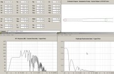
AkAbak PD1550 Tapped Horn
Here is a stripped down model of the PD1550 tapped horn described in my previous post. Actually Hornresp was used more, but I played around with extra cavities and reflectors in AkAbak. This model has all the extras stripped out for clarity and the AkAbak version posted as plain text. I've also removed the microphone response model and the crossover filters which were in for comparison with measurement.
Predicted cone displacement still to be measured, sometime.
Ken
| 20 Hz - 50 Hz Tapped Horn
| Single fold in box approx 2.4 by 0.4 by 0.4m uniform taper, not conical (but probably
| does not matter much for mild taper used)
Def_Const |Horn Dimensions
{
a1 = 320e-4; |Area at throat
a2 = 344e-4; |Area at rear of driver uncertain due to geometry
a3 = 1100e-4; |Area at front of driveruncertain due to geometry
a4 = 1120e-4; |Area at mouth
l1 = 20e-2; |Distance from throat to rear of driver
l2 = 440e-2; |Line distance from rear of driver to front of driver
l3 = 20e-2; |Distance from front of driver to mouth
}
|moderately insensitive to division of length among l1/l2/l3
|checked using Hornresp
Def_Driver 'pd1550'
SD=890cm2 dD1=10cm tD1=3.5cm
fs=31Hz Mms=123g Qms=5.55
Qes=0.22 Re=6ohm Le=2mH ExpoLe=0.618
|driver run in for a couple of weeks prior to measurement
|Le guess, not critical
system 'S1'
Driver Def='pd1550' Node=1=0=3=4
Waveguide 'W1' Node=2=3 STh={a1} SMo={a2} Len={l1} Conical
Waveguide 'W2' Node=3=4 STh={a2} SMo={a3} Len={l2} Conical
Horn 'H1' Node=4 STh={a3} SMo={a4} Len={l3} Conical HEdge=40cm WEdge=240cm
edit: tidied commets
Re: Re: Re: Tapped horns vs front loaded horns
I'm gonna give hornresp a go with a Eminance 4012, and see if I can get any good results...
Also, I've heard that folding a front loaded horn filters out harmonic distortion, I'm guessing this is true with TH's also?
My 4012's have a Fs of 45Hz, so I'll have to see what hornresp and Akabak make of it.
Well I was planning on using a DCX2496 for filtering, which has 48db/octive filters which should be good enough (i hope)... Plus having a smaller enclosure (than a front loaded horn) is always good.iand said:Tapped horns have the same distortion as a front-loaded horn with the same excursion -- which means better than a small front-loaded horn (loading is poor) but not as good as a huge one (excursion peaks are larger). Tapped horn distortion can be worse if a harmonic hits one of the out-of-band resonant peaks which can amplify it by 10dB or so (see below).
Below where the horn unloads you've only got the stiffness of the driver suspension (no rear chamber), so it won't take much to bottom the driver unless you use a driver optimised for a tapped horn which has higher Fs -- the ideal total compliance is the same as a front-loaded horn driver with sealed rear chamber, which typically means Fs<Fhorn for a normal horn and Fs>Fhorn for a tapped horn.
I'd say that the only significant disadvantage is the big high-Q peaks just above the passband, which don't get attenuated enough even with a 24dB/octave crossover and can amplify harmonic distortion.
To remove these you need either a *very* fast rolloff crossover (which means almost certainly digital), or to null out the peaks with quarter-wave resonator pipes like in the DTS-20 (which need tweaking and damping), or notch them out electronically using a parametric equaliser.
Of course a front-loaded horn with similar cutoff and ripple is much *much* bigger, it's not really a fair contest
Ian
I'm gonna give hornresp a go with a Eminance 4012, and see if I can get any good results...
Also, I've heard that folding a front loaded horn filters out harmonic distortion, I'm guessing this is true with TH's also?
I think i've pretty much decided on tapped then,Patrick Bateman said:
A couple more advantages:
- It's generally agreed that a tapped horn "tolerates" a driver with a higher FS. If you have two drivers of equivalent parameters, the one with the higher FS will have a higher sensitivity. This is often overlooked, and can add an additional DB or two to the overall output. One trend I've noticed in sealed box subwoofers is to use drivers with an FS in the teens. A driver like that almost invariably has a sensitivity in the low 80s. The tapped horns we've seen in this thread are sometimes using drivers with sensitivity ratings in the high 90s. That fact alone can contribute FIFTEEN db to the base efficiency of a tapped horn vs a sealed sub.
- It's damn near impossible to get a front loaded horn to go down to 15 or 20hz. Even the vaunted Lab Horn rolls off well before that. If you want to get bass at 20hz or lower, you're basically limited to bandpass, sealed, vented, tapped horn, transmission line and acoustic lever.
My 4012's have a Fs of 45Hz, so I'll have to see what hornresp and Akabak make of it.The DCX2469 is an excellent solution, both from the point of view of rapid rolloff crossover and parametric EQ to notch out the peaks. The big advantage is that it becomes trivial to make changes, especially if you're using the free PC control software instead of the front panel.
As was pointed out this doesn't prevent the distortion being picked out by the peaks, resonators are the best solution but I suspect a lot of experimentation tweaking is needed to get the diameter and length correct, to get the centre frequencies right with just the right amount of damping to get the correct Q.
Ian
references
Hi Naudio: have not had a lot of time lately, well what else is new, here are some links that may be helpful:
Post #1139/1146/1175: MaVo shows pictures of the interior of the DTS20; Post #1140 explanation by cowanaudio.
In Post #1147: Marcello provided a link to the tapped horn patents.
In Post #1174/1183: jnb shows the effect of a resonator in an AkAbak simulation, with and without damping (e.g.: polyfill stuffing in a PVC tube).
In Post #1187: Cordraconis presented his AkAbak for Dummies script with explanations for the individual elements.
Have fun!
- Home
- Loudspeakers
- Subwoofers
- Collaborative Tapped horn project