I've run sine sweeps on the horn in the past and not noticed any noise coming from the magnet - only rattles coming from other things in the house.Naudio said:hi long time no see
this question is mainly for mikehunt since we both built almost identical horns, just his is abit louder and mine goes abit lower
i find that if i am running my horn at very high levels there is a sorta noise or vibration coming from the speakers magnet, kinda like a pressure noise or summing, like its making a kinda vibrational noise that i think is only audible because it is at a higher frequency than the horn is making but away from the horn u cannot hear it, does anyone else find this with tapped horns?
maybe u have the same issue with yours and its normal, just it sounds like summing lose in the driver but its the same as day 1, maybe i got a slightly dodge driver or make i have stretched it (dont see how)
any ideas?
 Mine will exceed Xmax at around 40Hz if I put more than 100W into the driver, and I have done this in the past as my amp does 200W per chan.
 Check the cone displacement graph for your design, you may be doing something similar? Also, if you haven't already, try slow sine sweep. This is easy anough with the siggen built into WinISD and a laptop connected to your amp.
This is definately audible when I exceed Xmax so I now have my limiter so it won't exceed xmax at 40Hz.
Also, if this is your first build, it may be worth checking for the usual suspects, air leaks, driver mounting, etc.
Re: How is this different from a transmission-line? It's not a horn!
Edit- Oh, and this topic from the start -edit
Regards Johan
http://danleysoundlabs.com/pdf/danley_tapped.pdfOriginally posted by methylamine I would love to be educated in the Tapped Horn principle
Edit- Oh, and this topic from the start -edit
Regards Johan
Re: How is this different from a transmission-line? It's not a horn!
Tapped TLs, horns (TP, TH) are 6th order band-pass (BP) alignments taken to their logical extreme, morphing the separate chambers and vents into one long, continuous chamber.
If it expands, it's a horn. If it doesn't, it's a TL. If it's reverse tapered, it's a TQWT. Due to minimizing their size they tend to have two distinct gain BWs consisting of a lower TL modes one where the mouth is too small/horn too short and a higher gain one as its length/mouth becomes long/large enough to support 1/2 WL horn action. Use the right driver specs for the desired alignment and it will have full horn action.
Note that this is just an example, not a real driver AFAIK. Sim is 2 pi (half space) and is 3251.784 L, proving tapped horns don't defy any physical laws AFAIK:
GM
methylamine said:I would love to be educated in the Tapped Horn principle...but to me, it looks like a modified transmission line speaker, NOT a horn.
Tapped TLs, horns (TP, TH) are 6th order band-pass (BP) alignments taken to their logical extreme, morphing the separate chambers and vents into one long, continuous chamber.
If it expands, it's a horn. If it doesn't, it's a TL. If it's reverse tapered, it's a TQWT. Due to minimizing their size they tend to have two distinct gain BWs consisting of a lower TL modes one where the mouth is too small/horn too short and a higher gain one as its length/mouth becomes long/large enough to support 1/2 WL horn action. Use the right driver specs for the desired alignment and it will have full horn action.
Note that this is just an example, not a real driver AFAIK. Sim is 2 pi (half space) and is 3251.784 L, proving tapped horns don't defy any physical laws AFAIK:
GM
Attachments

Hey all,
I posted some of this quite a while ago.
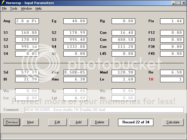
I built this box using AKABAK as my design tool originally.
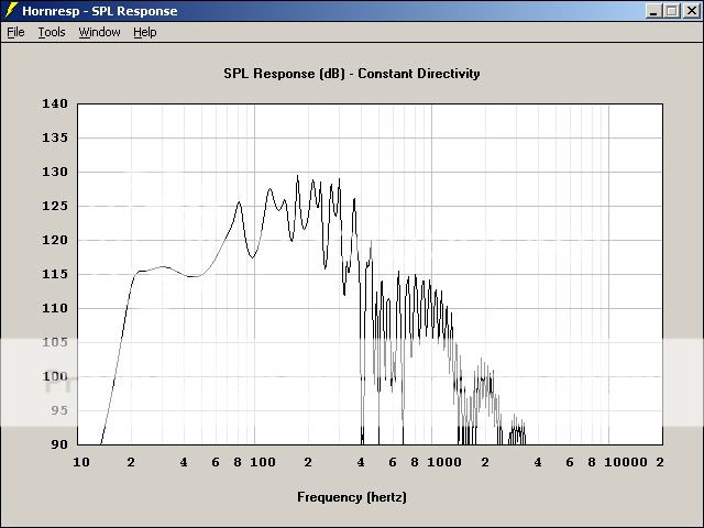
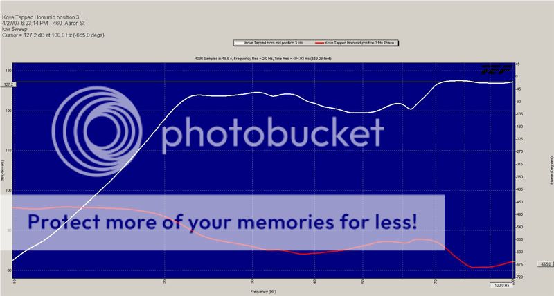
Playing around with Mc Beans TH simulator I got it to more closely match my measured response.
I started with the DTS-20 OD as my limiting factor.
Playing with AKABAK it was immediately obvious that single fold wasn't going to get anywhere near 20Hz.
Heres what I ended up with.
Fun stuff.
Whats all this I hear about people using the Lab 12 in a Tapped horn??
I think it would have to be huge, has anyone made one that the XMAX of a LAB 12 would stay under control across its power band?
I posted some of this quite a while ago.
I built this box using AKABAK as my design tool originally.
Playing around with Mc Beans TH simulator I got it to more closely match my measured response.
I started with the DTS-20 OD as my limiting factor.
Playing with AKABAK it was immediately obvious that single fold wasn't going to get anywhere near 20Hz.
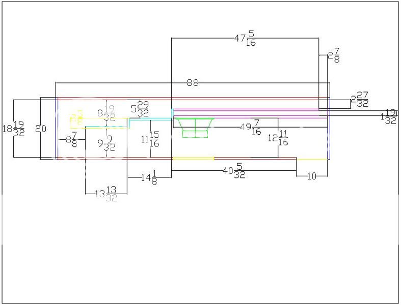
Heres what I ended up with.
An externally hosted image should be here but it was not working when we last tested it.
An externally hosted image should be here but it was not working when we last tested it.
An externally hosted image should be here but it was not working when we last tested it.
Fun stuff.
Whats all this I hear about people using the Lab 12 in a Tapped horn??
I think it would have to be huge, has anyone made one that the XMAX of a LAB 12 would stay under control across its power band?
GM: thank you for the reply, I'm reading now
Coming from such a traditional horn background, I'm not sure I follow this, but I'm studying it now.
Thank you for the reply! What a fascinating study this is.
Has anyone done a frank A vs. B comparison, with either an exponential horn or ported box, versus a Tapped Horn, with actual SPL measurements on a sin sweep?
I think its the discontinued Z12D
It was from a parts express buyout.
I found any TS parameters I found on it wrong.
I had to use the Mass added technique to solve find the true TS parameters.
Antone-
It was from a parts express buyout.
I found any TS parameters I found on it wrong.
I had to use the Mass added technique to solve find the true TS parameters.
Antone-
When you are "adding inductance" to your tapped horn, do you put the inductor in a series with one of the speaker wires, or does it go in between the positive and negative (parallel)?
I have one of the two tapped horns completed, havent 'added the inductance' yet, but the lightning strike on the thx intro sounded very tight and smooth.
I have one of the two tapped horns completed, havent 'added the inductance' yet, but the lightning strike on the thx intro sounded very tight and smooth.
Right or wrong i put in in series with the positive speaker cable wire, and wow! ...I don't really know why I am building two of these things...
Chris,
You did right. Just put the inductor in series (plus or minus, doesn't matter).
Got some pictures? How did the construction go? Any suggestions for improving it?
You did right. Just put the inductor in series (plus or minus, doesn't matter).
Got some pictures? How did the construction go? Any suggestions for improving it?
It sounds WAY better than a sealed Dayton DVC, a ported Dayton Reference, a Sealed Dayton Reverence, a sealed lab 12, and a ported lab 12. Those are the only DIY subs I have done. Obviously it outperforms anything commercial I have ever heard too. Nothing I have heard comes close to the clarity and "cleanness" that this is putting out. I know for a fact that I in no way shape or form need two of these things.
All that is left on the second one is to glue it together. I made an access panel right above the driver and used a small cutout with a diameter of about 7 inches. I then used the disk that was cut out for the driver hole in the baffle to go over the access hole. That saved alot of time. It was a little tight getting the wrenches into the small space between the driver and the wall to screw it in place, but it is doable, its just not fast.
I should have some pics up fairly soon, but I may not get a chance to complete the second one until next weekend.
Thanks to everyone who contributed to this thread, designed this model and folded the horn up for me.
Yes Don Bunce has built some (see near post 100) and MaVo has some sims that look good around post 1400. None of them look much bigger than yours. I have 4 of the drivers and are still procrastinating on building them. I'll get all the wood cut when I do the main and side speakers next month.sumsound said:
Whats all this I hear about people using the Lab 12 in a Tapped horn??
I think it would have to be huge, has anyone made one that the XMAX of a LAB 12 would stay under control across its power band?
Re: Chris's new LAB12 TH
Hello guys,
FWIW, sumsound's DT-20 clone is over 500 L, MaVo's sim is 348 L, and mine (attached) is 321 L. Hornresp says that mine will XMAX out with a 25 Hz sine wave at 90 Watts, but it still sounds great at 150 Watts. It should handle 300 Watts of music.
The Driver can be installed thru the mouth. It isn't easy, you gotta do it by feel, but it's not as hard as reaching the oil filter on my truck. It just requires a piece of 3/16 dowel to center the speaker over the T-Nuts, and it helps to use 1/4-20 socket head cap screws and a hex screw driver. That way, the tool doesn't slip and punch a hole in your driver's cone.
Here is a cleaned-up version of the earlier posting, with some dimensions rounded to the nearest 1/8 inch, and the throat piece and required inductor defined.
Attachments

Don Snyder said:Re: Chris's new LAB12 TH
Hello guys,
FWIW, sumsound's DT-20 clone is over 500 L, MaVo's sim is 348 L, and mine (attached) is 321 L. Hornresp says that mine will XMAX out with a 25 Hz sine wave at 90 Watts, but it still sounds great at 150 Watts. It should handle 300 Watts of music.
The Driver can be installed thru the mouth. It isn't easy, you gotta do it by feel, but it's not as hard as reaching the oil filter on my truck. It just requires a piece of 3/16 dowel to center the speaker over the T-Nuts, and it helps to use 1/4-20 socket head cap screws and a hex screw driver. That way, the tool doesn't slip and punch a hole in your driver's cone.
Here is a cleaned-up version of the earlier posting, with some dimensions rounded to the nearest 1/8 inch, and the throat piece and required inductor defined.
Wow I'm impressed thats very efficient for so low power. Have you verified the output?
Oh wait your set to 1/8th space.
Ok both of them Are Ok, but It looks like fun!!!
Newbie - check my understanding
I just got around to playing with the TH features of horn resp. It took me a while to get the idea but I think I am getting there. The way I approached it was to set up three conical segments of equal length and taper providing the total length and mouth area that I wanted.
I then started the TH wizard and adjusted driver positions for the smoothest and broadest response. The best results were generally with the driver located rather close to the ends of the horn. Mouth size was not as critical as I would have believed.
Does that sound like typical results? It also appears that the low frequency cut off is almost entirely determined by line length, correct?
Also if I am understanding correctly the driver positions simply represent the distance of the tap from each end. How you fold it to achieve that is really of little consequence right?
It appears that HR is modeling with the opening on the end (i.e. axis of the the mouth opening is basically perpendicular to the driver's axis). However a lot (most?) designs I have seen have the end closed off and the mouth axis essentially parallel to the driver axis (looks like a big port). How does one determine the length/distange from the mouth for the latter approach? Is the end of the mouth half way across the opening?
Sorry if I am not clear, it is a little hard to describe.
BTW, a 15" organ speaker in a 20 foot long line looked like a very nice under floor subwoofer option. 😀
Chris8sirhC said:I thought it could handle 141 watts at 20 hz?
Sims are sims. Once you have the physical horn, you can test and find out how good it really is. Hornresp sims 90 Watts at 25 Hz, but Tapped Horns typically measure 60% to 70% higher than Hornresp shows. That's 144 Watts at 25 Hz. I would bet money that your speaker will take 300 Watts at 20 Hz and above 35 Hz.


- Home
- Loudspeakers
- Subwoofers
- Collaborative Tapped horn project