Hi TundraLD,
All models assume that drivers are linear all the way up to Xmax and don’t suffer from power compression, changing characteristics, changing resistance and so on. Our models only show ideal behaviour from an ideal sinus signal that do not represent the complexity from signals like music. Therefore in our real world the predicted SPL and excursion will not be reached with the calculated power. If you power them enough so they will reach their Xmax, the excursion below the excursion dip can become unstable/uncontrolled. Therefore in most cases TH’s for PA could be best cut at or just below their excursion dip if you want to use them to. You also can improve excursion stability below the excursion dip by applying a slot opening in the throat of a TH. The ideal form of such slot is still being discussed.
For Art:
The model you are using in your post# 498 for your Keystone shows different resonance points at different locations from your measurements. Also is the SPL response very different. I think your model is not a good representation because it doesn’t represent the right volumes at the right spots.
Your measurement:
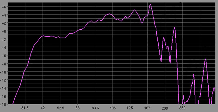
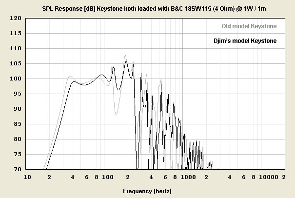
Differences in my model with your model (compare the response and resonance points") ):
):
All models assume that drivers are linear all the way up to Xmax and don’t suffer from power compression, changing characteristics, changing resistance and so on. Our models only show ideal behaviour from an ideal sinus signal that do not represent the complexity from signals like music. Therefore in our real world the predicted SPL and excursion will not be reached with the calculated power. If you power them enough so they will reach their Xmax, the excursion below the excursion dip can become unstable/uncontrolled. Therefore in most cases TH’s for PA could be best cut at or just below their excursion dip if you want to use them to. You also can improve excursion stability below the excursion dip by applying a slot opening in the throat of a TH. The ideal form of such slot is still being discussed.
For Art:
The model you are using in your post# 498 for your Keystone shows different resonance points at different locations from your measurements. Also is the SPL response very different. I think your model is not a good representation because it doesn’t represent the right volumes at the right spots.
Your measurement:
Differences in my model with your model (compare the response and resonance points
):
Last edited:
Djim,Therefore in most cases TH’s for PA could be best cut at or just below their excursion dip if you want to use them to. You also can improve excursion stability below the excursion dip by applying a slot opening in the throat of a TH. The ideal form of such slot is still being discussed.
For Art:
The model you are using in your post# 498 for your Keystone shows different resonance points at different locations from your measurements. Also is the SPL response very different. I think your model is not a good representation because it doesn’t represent the right volumes at the right spots.
The Keystone exit shape can not be modeled with Hornresp, the simulation used simply represents the physical path length, shape and cabinet volume.
In the actual Keystone cabinet, to get the LF the sim predicts caused upper frequency response problems.
The Keystone exit took dozens of prototypes to derive the best compromise between top and bottom response.
I opted to loose a few Hz at the bottom for a smoother and more extended top, if one were crossing at 80 Hz (or lower) rather than 100 Hz, a different exit could be used providing more LF.
In fact, the Keystone exit as built can be reduced and get "flat to 30 awsomeness", a "step down mode" plate can be bolted on for the few gigs that require a bit lower response.
The chart below shows some of the various response curves possible with the simple addition of a small external piece of plywood.
Of interest, I tried applying a slot opening in the throat of the Keystone, it did not improve either excursion control, or frequency response.
PASC has noted in his comparison:
"Measured the TH18 Xoc1 and it stops at 117dBs using similar power as input for this driver in the Keystone (past 2300Wrms 8ohms loaded, without clipping the Machine AB+H 9400 amp).
Changed the drained battery for one with full 9V and goes to 126.2 peak holder from 38 ~ 97Hz band, also with very good hi-fi sound, and a bit better defined says my friend who also plays bass guitar.
The cone control IMO, wasn’t as good as in the Keystone, which sound I preferred, maybe because I’ve owned a DJ PA in past, where lows are more present than at live music that my friend is more used to."
Having not compared the two designs using the same speaker, I can only defer to PASC, but having hit the BC18SW115-4 loaded Keystone with as much power as I have available, it still sounds clean when other speakers sound like they are coughing their guts out
.Art
Attachments
Hi Art,
The Keystone mouth is much less of a mystery as you might think. It is actually not that difficult to simulate in HornResp if you do it right. I do agree that above its full wavelength it become less accurate. This counts for most models from HornResp because HornResp 'sees' no forms (like the extra volume of corners) but only 'sees' the general layout and its volume in an ideal way.
The problem with the HornResp model you are using, is that is based on wrong inputs. The centre for the Keystone mouth is wrong positioned which makes the total length of the hornpath way too long! The extra volume between the driver and the mouth is not represented at all in the model you are using. If you look carefully to my model you will see it is much more accurate and the resonance points are located very accurately. But it needs better CAD modelling to be more precise. If you are interested I can share in detail, in your Keystone thread if you want.
As you already know, I also agree that symmetric circular narrowing of the mouth will not improve excursion stability nor does it improve LF extension. It does not in our models and it does not in reality. The form for this narrowing is the key for successful improvement and yes it is possible.
About PASC’s comments, his story is a little unclear to me. He measures the Xoc1-TH18 with a 18Sound 18LW2400, that has a AES power rating of 1200W.
Quote PASC: "Bellow 38Hz cone control is absent with 18LW2400 at Pe limit."
Therefore it is no surprise his driver will become unstable after more than 2Kw continue sine wave, don’t you think? (Ps how many driver are stable at twice their AES power rating?!)
The Xoc1-TH18 loaded with a 18Sound 18LW2400 does allow 1800 Watts (1.5 x AES power) without any excursion problem with the low cut at 33Hz. If you want to use this driver in the Xoc1-TH18 with the full 2400 Watts, I would use a low cut above 37Hz (measure the impedance to pinpoint the exact frequency) .
The Cox1-TH18 loaded with the B&C 18SW115 (4Ohm!) does give low end extension by a couple of Hertz but more importantly it is a couple of dB’s louder in sensitivity, below 38Hz, compared to the (half price) 18Sound 18LW2400.
Last edited:
Hi Djim!
Where have I stated continue sine wave?
I'm not crazy yet. Maybe a little bit, but...
By me sine waves are only used to make sweep tests to see what the response (around 1W), to take T/S parameters, and to brake in a driver, but this at 1/4 Pe limit = AES amount (that numbers made or made up, with low cut of 40Hz-more than 3dBs bellow using pink noise... to rise SPL = sensibility numbers for the incautious who cannot interpret it, be impressed).
Cleared that, I would say that time that the 18LW2400 barely can take 1200W, with pink noise or music, also obvious with the low cuts stated (38Hz till 96Hz LR 24); increase power and the cone travels insanely; don't try low cut at 30Hz with that kind of power from real amps capable to sustain and surpass 2300WRMS continuous, 8 ohms p/c, not that today's ms ****;
After 18LW2400 we tried 18TBX100, which allowed more power, with better control, but final SPL would be around same program (pink noise and music).
Than put the 18NLW9600 in and cone control was OK with same band, with around a dB peak more than the 18TBX100. If you had the money for 18 Sound 18NLW9600 and or a B&C 18SW115, 4 ohms would be my choice. If not, play 3 dBs less at power amp and you will have near same.
Keystone, I tried only with the 18NLW9600, which with mouth restriction allowed 2300WRMS easily, peaking above 128dBs, with good cone control.
Also tried other low cuts from 25Hz above till 200Hz, cone control remains and sound was always Hi-fi, nearly flat.
Sorry for no good picture but was the only one taken when band was 25 till 200Hz
http://img1.uploadhouse.com/fileuploads/15697/15697991444701e63930c6dffaac2cf781d5df5b.jpg
So think it can be used for DJ and live music.
Would not use a sub past 100Hz.
Made THs for 6”, 12”, 15” and 18” drivers, and always cone control was the problem in box; that's why a restriction at throat or at mouth will give results; think only a few drivers from the candidates will actually do well innit, playing all the bass guitar notes at same level and defined as they are played live; why? because I will hear music thru the loudspeaker.
So a friend, bass guitar player, will help me to make good choices.
Regards,
Hi Pasc,
Lol…. But my quote comes from your post (click the link in my earlier post) “Bellow 38Hz cone control is absent with 18LW2400 at Pe limit”
But thanks for clearing up so quickly. It does make me curious about your method of measuring Power. We didn’t have any problems powering the 24LW2400 up till 1800 Watts (complex noise burst following AES/IEC guidelines and power measured by current/voltage method to prevent calculation errors from thermal rising of the Re). It was beyond the 1800 Watts when excursion became unstable and yes at 1800 Watts it shows quiet some excursion, sill far below Xlim. All four cabs (including mouth and ‘broom’ bracing as suggested in my earlier post) are build/owned by a hardstyle DJ, who punish them with a Labgruppen FP9000 (2 cabs per channel, cut at 36Hz -110Hz / 48dB/oct) and no driver has returned since… To be honest I don't think this driver will do any better in the Keystone.
The B&C drivers 18SW115 are tested by somebody else but I have no reason to doubt his findings.
Lol…. But my quote comes from your post (click the link in my earlier post) “Bellow 38Hz cone control is absent with 18LW2400 at Pe limit”
But thanks for clearing up so quickly. It does make me curious about your method of measuring Power. We didn’t have any problems powering the 24LW2400 up till 1800 Watts (complex noise burst following AES/IEC guidelines and power measured by current/voltage method to prevent calculation errors from thermal rising of the Re). It was beyond the 1800 Watts when excursion became unstable and yes at 1800 Watts it shows quiet some excursion, sill far below Xlim. All four cabs (including mouth and ‘broom’ bracing as suggested in my earlier post) are build/owned by a hardstyle DJ, who punish them with a Labgruppen FP9000 (2 cabs per channel, cut at 36Hz -110Hz / 48dB/oct) and no driver has returned since…
To be honest I don't think this driver will do any better in the Keystone.The B&C drivers 18SW115 are tested by somebody else but I have no reason to doubt his findings.
Last edited:
Hi!
First time I see this 24LW2400 being mentioned.
This must move some air; but also the cone must weight a lot to not bend and sensibility should be lower. Own you the T/S.
Is it a new driver from 18 Sound as it not appears at their site yet? Will contact local dealer.
Regards,
First time I see this 24LW2400 being mentioned.
This must move some air; but also the cone must weight a lot to not bend and sensibility should be lower. Own you the T/S.
Is it a new driver from 18 Sound as it not appears at their site yet? Will contact local dealer.
Regards,
Hi!
As think I known what happens when abuse the driver above its thermal and mechanical limits as well as how it affect it's longevity (and how I will make glad factory which sells and the reconing service will be within it = what comes first).
One year of normal use within limits is enough to loosing to much the spyder of the driver tells a big loudspeaker factory owner; this will change the T/S parameters a bit and so the predicted response...
So why have I to surpass these limits when I know what will happen, only to have between a dB or two more and at what cost?
Hardstyle DJ isn't a problem when he is well instructed and red lights of control desk are avoided; if lowcuts are proper like mentioned, beside amps like this famous one, which helps to mantain things working, avoiding clips and when power is peak power. If not a compressor will help.
As I know little from this well named and expensive amp, and specs downloaded from factory site, and this one isn't tested by abeltronics, can you give me more details on it.
Like what I read on PDF:
Peak total output both channels driven - 9000W
Maximum output power P/C both working 4500W-2ohms, 3000W-4ohms, 1600W-8 ohms, 800W-16 ohms
Bridged...
I cannot read continues power.
But read "all the power all the time".
To also clear, is it continues (senoidal thru) measured WRMS, till senoidal signal remain curved at top and bottom at oscilloscope window like old school, when we put a shower resistance plugged to the amp output, immersed into a barrel full of water (due to that big power), or are these impressive numbers sustainable for how many ms?
Thanks and regards,
Most high power amplifiers can not sustain full power without blowing a circuit breaker, the breaker value compared to the efficiency factor would determine how much power it can put out long term.As I know little from this well named and expensive amp, and specs downloaded from factory site, and this one isn't tested by abeltronics, can you give me more details on it.
Like what I read on PDF:
Peak total output both channels driven - 9000W
Maximum output power P/C both working 4500W-2ohms, 3000W-4ohms, 1600W-8 ohms, 800W-16 ohms
Bridged...
I cannot read continues power.
But read "all the power all the time".
To also clear, is it continues (senoidal thru) measured WRMS, till senoidal signal remain curved at top and bottom at oscilloscope window like old school, when we put a shower resistance plugged to the amp output, immersed into a barrel full of water (due to that big power), or are these impressive numbers sustainable for how many ms?
As an example, a QSC PLX 3602 would draw 63 volts at 120 VAC, though it can put out it's rated 3600 watts, it will blow it's breaker in about two seconds at rated power.
It will also blow the breaker when called to do really heavy compressed bass music in to 2 ohm loads.
Art
Lol, sorry my typing mistake. Of course it should be 18LW2400. Maybe a couple of new drivers will be presented at the next Prolight + Sound convention in Frankfurt (21 till 24 of March). About the Labs, often they do even a little better as their specs suggest. For non commercial applications they are (too) expensive but they have their own quality. There are cheap Chinese clones of which a few seem to do a very similar job at a ridiculous low price.Hi!
First time I see this 24LW2400 being mentioned.
This must move some air; but also the cone must weight a lot to not bend and sensibility should be lower. Own you the T/S.
Is it a new driver from 18 Sound as it not appears at their site yet? Will contact local dealer.
Regards,
Last edited:
Please do, I have a design using dual Lab12s in a tiny 83 liter box Hornresp predicts will do 124 dB flat 40 Hz to 100 Hz (half space full power, no HP needed) that I'd like to get right before cutting wood, as it won't allow adjustments after the build that the Keystone did.Hi Art,
The Keystone mouth is much less of a mystery as you might think. It is actually not that difficult to simulate in HornResp if you do it right. I do agree that above its full wavelength it become less accurate. This counts for most models from HornResp because HornResp 'sees' no forms (like the extra volume of corners) but only 'sees' the general layout and its volume in an ideal way.
If you look carefully to my model you will see it is much more accurate and the resonance points are located very accurately. But it needs better CAD modelling to be more precise. If you are interested I can share in detail, in your Keystone thread if you want.
I hate wasting plywood.
Art
We didn’t have any problems powering the 18LW2400 up till 1800 Watts (complex noise burst following AES/IEC guidelines and power measured by current/voltage method to prevent calculation errors from thermal rising of the Re). It was beyond the 1800 Watts when excursion became unstable and yes at 1800 Watts it shows quiet some excursion, still far below Xlim. All four cabs (including mouth and ‘broom’ bracing as suggested in my earlier post) are build/owned by a hardstyle DJ, who punish them with a Labgruppen FP9000 (2 cabs per channel, cut at 36Hz -110Hz / 48dB/oct) and no driver has returned since…
The B&C drivers 18SW115 are tested by somebody else but I have no reason to doubt his findings.
The Xoc1-TH18 loaded with a 18Sound 18LW2400 does allow 1800 Watts (1.5 x AES power) without any excursion problem with the low cut at 33Hz. If you want to use this driver in the Xoc1-TH18 with the full 2400 Watts, I would use a low cut above 37Hz (measure the impedance to pinpoint the exact frequency) .
The Cox1-TH18 loaded with the B&C 18SW115 (4Ohm!) does give low end extension by a couple of Hertz but more importantly it is a couple of dB’s louder in sensitivity, below 38Hz, compared to the (half price) 18Sound 18LW2400.
Hi Djim
Very pleased to hear about positive results.
This is very useful information for other prospective builders and users.
Its obvious that you have taken care with your measurements. Have you been holding out on us, this is the first I have heard about these builds!
Have you any more details you would like to share?
I think that it would definitely be worth looking into the Keystone TH design more closely. Whatever Art has done it it definitely working.Hi Art,
The Keystone mouth is much less of a mystery as you might think. It is actually not that difficult to simulate in HornResp if you do it right. I do agree that above its full wavelength it become less accurate. This counts for most models from HornResp because HornResp 'sees' no forms (like the extra volume of corners) but only 'sees' the general layout and its volume in an ideal way.
The problem with the HornResp model you are using, is that is based on wrong inputs. The centre for the Keystone mouth is wrong positioned which makes the total length of the hornpath way too long! The extra volume between the driver and the mouth is not represented at all in the model you are using. If you look carefully to my model you will see it is much more accurate and the resonance points are located very accurately. But it needs better CAD modelling to be more precise. If you are interested I can share in detail, in your Keystone thread if you want.
As you already know, I also agree that symmetric circular narrowing of the mouth will not improve excursion stability nor does it improve LF extension. It does not in our models and it does not in reality. The form for this narrowing is the key for successful improvement and yes it is possible.
Art built many variations of his cabinet to find the sweet spot. The TH18 is CAD and Sim only. I first posted this design 10 months ago and we are still looking for a way to improve on it.
I still think that the throat is the key to getting the last bit of control out of the TH18 design. Squeezing down the throat area is definitely possible. Josh Ricci has shown that higher compression in the throat is practical. Also reducing the throat opens up the possibility of increasing the path length.
David McBean recently posted on the Hornresp thread that VTC should include the cone volume, but how many of us are even bothering to do that!
I think that the offset nature of the TH throat is more complicated than the Hornresp model.
Imagine a sim where S2 is reduced to almost zero. The reported compression ratio would be massive, but in reality there would still be a conciderable cross sectional area at the S2 point, due to the baffle cut out and the actual shape of the speaker cone.......
Regards
Martin (Xoc1)
Martin,David McBean recently posted on the Hornresp thread that VTC should include the cone volume, but how many of us are even bothering to do that!
I think that the offset nature of the TH throat is more complicated than the Hornresp model.
Imagine a sim where S2 is reduced to almost zero. The reported compression ratio would be massive, but in reality there would still be a conciderable cross sectional area at the S2 point, due to the baffle cut out and the actual shape of the speaker cone.......
Regards
Martin (Xoc1)
Since Hornresp uses a flat piston as the model, if S2 is reduced, the compression ratio would be massive unless VTC is representative of the cone area.
Modeling with S1 and S3 of the same area and S2 reduced with VTC including the cone volume does give slightly different response curves from the way you modeled the TH18, though they may still not reflect the actual response or the "cone control" that may result.
Art
Hi Martin,
You are basically talking about introducing a choke point at the S2 location, but when you do that in Hornresp the tapers of both, the S1 to S2 and the S2 to S3 sections get changed. One way you may get close is to add all the length from S2 to S3 into L34, and setting the new S3 to the old S2. Then set L23 real short e.g.: 1cm. That way you can choke S2 without affecting the taper from the old S2 (now S3) to S4. You can still adjust S1 and L12 to suit. The other point where you can squeeze the output of the throat chamber is through the area and length of the coupling element Ap1/Lpt. The throat chamber will still be the cone volume plus any spacer volume (it does not seem to be very critical in Hornresp). It is important to remember, that Hornresp does not model frictional-or other-losses.
Regards,
Hi Martin,
The actual build I was talking about are not our creations and the owner/builder is a client so we had limited time to do serious testing. He was tired carrying our heavy dual 18inch basreflex designs (Monacor loaded) any longer and prepared to give up some low end extension in favour of higher SPL’s. Yesterday I heard from my colleague he changed the compressors in his crossover so I am wondering how long it will take before we see any of his drivers back in our workshop.
You can design a negative of the cone volume that you can attach to the panel it is facing for correcting the cone volume in order to correct S2. However, it does not correct the impedance differences between the left side and the right side of the driver nor does it correct the location of the high pressure zone to the centre of the driver, as we discussed. For that, I do believe the best solution so far, I already showed in post#172 of the "18TBX100 vs 2lab12" thread (see same picture below) is the best way to go from. This is a rough example and I am still working on the shapes. However I still prefer to have the lowest narrowing/throat compression possible since it only creates more losses and often makes the usable bandpass smaller besides the doubts mentioned earlier.

I am also still working on the text of Art’s Keystone but my limited CAD skills make it even more time consuming besides my horrible writing speed
The actual build I was talking about are not our creations and the owner/builder is a client so we had limited time to do serious testing. He was tired carrying our heavy dual 18inch basreflex designs (Monacor loaded) any longer and prepared to give up some low end extension in favour of higher SPL’s. Yesterday I heard from my colleague he changed the compressors in his crossover so I am wondering how long it will take before we see any of his drivers back in our workshop
. You can design a negative of the cone volume that you can attach to the panel it is facing for correcting the cone volume in order to correct S2. However, it does not correct the impedance differences between the left side and the right side of the driver nor does it correct the location of the high pressure zone to the centre of the driver, as we discussed. For that, I do believe the best solution so far, I already showed in post#172 of the "18TBX100 vs 2lab12" thread (see same picture below) is the best way to go from. This is a rough example and I am still working on the shapes. However I still prefer to have the lowest narrowing/throat compression possible since it only creates more losses and often makes the usable bandpass smaller besides the doubts mentioned earlier.
I am also still working on the text of Art’s Keystone but my limited CAD skills make it even more time consuming besides my horrible writing speed
Thanks for all the replies Lots to take in and concider!
We all know that Hornresp has limitations when it comes to tapped horn design.
It is relatively easy to take the Hornresp model and export it into Akabak to add extra sections.
Perhaps a more simplistic approach would be to ignore the Vtc and Atc settings but compensate for the physical volumes of the speaker cone and baffle board by the shape of the throat section.
As I have said before the compression ratio reported at S2 by Hornresp seems wrong to me. At this point in a offset TH horn if we imagine the piston of the speaker moving in and out, 50% of the air that is displaced /compressed in the throat does not even get to the S2 point in the horn.
Also to use a ramp that tapers from S1 to S2, as in the Othorn for instance, seems wrong to me. It might give better efficiency higher in the passband in a hornresp model, but why does the taper not continue right across the face of the speaker - as it does in some classic FLH designs. Is it because it performs better, or is it because it is easier to sim?????
This might take some time to resolve. Not much spare time at the moment.
A good start might be to get some data together on the actual physical shapes of some of our favourite speaker cones,
Regards Martin (Xoc1)
Driver Dimension Request
I have sketched out the throat area of the TH18 and the PDF shows the cross sectional area at S2 - Hornresp calculated S2 area being 460 cm sq and actual area being approximately 729 cm sq!
I say approximately as I do not have any 18" drivers at hand to measure.
I have added some dimensions:-
Suspension outer (or inner diameter of the basket) A
Cone Diameter B
Dust Cap Diameter C
Suspension Ht from mounting face D
Cap Ht from mounting face E
Cone Depth from mounting face F
If anyone has some suitable drivers to hand, that could measure these dimensions to get a more accurate model it would be appreciated.
Regards
Martin (Xoc1)
Attachments
I have sketched out the throat area of the TH18 and the PDF shows the cross sectional area at S2 - Hornresp calculated S2 area being 460 cm sq and actual area being approximately 729 cm sq!
I say approximately as I do not have any 18" drivers at hand to measure.
I have added some dimensions:-
Suspension outer (or inner diameter of the basket) A
Cone Diameter B
Dust Cap Diameter C
Suspension Ht from mounting face D
Cap Ht from mounting face E
Cone Depth from mounting face F
If anyone has some suitable drivers to hand, that could measure these dimensions to get a more accurate model it would be appreciated.
Regards
Martin (Xoc1)
Just for the heck of it it measured the 18SW115. Taking into consideration the the volume of air in the 18mm (circular) baffle cutout and the Air Volume (Vtc) in front of the driver is approximately 4920cc. I know the discussion lately has brought up that none of us have really taken Vtc into consideration
Played with my Akabak script a little more tonight. If anyone want to play with it I added some drivers. Just remove the block on the T/S line for the driver you want to run. Added the VTC from measuring one of my B&C 18SW115 drivers. I'm still learning things in Akabak so don't be to hard on me if you find mistake let me know
COPY BELOW THIS LINE
|Rev5 - Model based on how geitmans built the spud script and now accounting for Vtc
|TH-18 Flat to 35hz! (Xoc1's design) on DiyAudio.com Collaborative effort
|I have not taken into account the bracing as it makes my head spin adding so many sections of script (I am working on it though)
|TundraLTD Enjoy!!
|=================================================================================================================================================================
|Network node numbers for this tapped horn system:
| 0-Voltage-1
| |
| -Chamber-5-Driver-------------------------------------------------------------------------------------------------------------
| | |
|8-Duct-9-Duct-10-Duct-11-Duct-12-Duct-13-Duct-14-Duct-15-Duct-16-Duct-17-Duct-18-Duct-19-Duct-20-Duct-21-Duct-22-Duct-23-Duct-24-Duct-25-Duct-26-Duct-27-Radiator
|=================================================================================================================================================================
Def_Const | Data for Vtc Chamber
{
Vtc = 4923.00e-6; |Throat chamber volume (cubic m)
Atc = 1210.00e-4; |Throat chamber cross-sectional area (sq m)
Sd = 1210.00e-4; |Diaphragm area (sq m)
Ltc = Vtc / Atc;
}
Def_Driver 'Driver'
|READ THIS
|Simply remove the block for the driver you wish to Sim
| <-block (in front of Sd) REMEMBER to only have one drive unblocked at a time
|18Sound 18LW2400-8
| Sd=1225.00cm2 Bl=25.77Tm Cms=1.07E-04m/N Rms=5.90Ns/m fs=35.0003Hz Le=1.35mH Re=5.00ohm ExpoLe=1
|B&C 18SW115-8
| Sd=1210.00cm2 Bl=28.31Tm Cms=1.21E-04m/N Rms=10.10Ns/m fs=30.9998Hz Le=1.70mH Re=5.10ohm ExpoLe=1
|B&C 18TBW100-8
| Sd=1210.00cm2 Bl=30.07Tm Cms=8.38E-05m/N Rms=6.78Ns/m fs=35.0003Hz Le=2.45mH Re=6.50ohm ExpoLe=1
|Precision Devices PD1850-8
| Sd=1150.00cm2 Bl=31.41Tm Cms=1.32E-04m/N Rms=6.65Ns/m fs=29.9999Hz Le=1.00mH Re=5.40ohm ExpoLe=1
|BMS 18N850v2-8
| Sd=1213.00cm2 Bl=25.11Tm Cms=1.18E-04m/N Rms=6.10Ns/m fs=29.7001Hz Le=0.89mH Re=5.00ohm ExpoLe=1
|Void Acoustics V18-1000-8
| Sd=1230.00cm2 Bl=34.96Tm Cms=9.35E-05m/N Rms=6.46Ns/m fs=34.5311Hz Le=2.20mH Re=5.50ohm ExpoLe=1
|18Sound 18NLW9600-8
| Sd=1134.00cm2 Bl=30.55Tm Cms=8.13E-05m/N Rms=6.62Ns/m fs=33.9997Hz Le=2.11mH Re=4.70ohm ExpoLe=1
System 'System 1'
Filter 'HighPass' |Highpass filter - 12dB Butterworth (change 'fo=***' and refresh for changes)
fo=31Hz vo=1
{b2=1;
a2=1; a1=1.414214; a0=1; }
Filter 'LowPass' |Lowpass filter - 48dB Butterworth (change 'fo=***' and refresh for changes)
fo=100Hz vo=1
{b0=1;
a8=1; a7=5.125831; a6=13.137071; a5=21.846151; a4=25.688356; a3=21.846151; a2=13.137071; a1=5.125831; a0=1; }
Driver Def='Driver'
Node=1=0=25=5
Duct 'Throat chamber' Node=5=9 SD={Atc} Len={Ltc} visc=1
Duct 'D1' Node=8=9 HD=53.5cm WD=5cm Len=21.92cm visc=50
Duct 'D2' Node=9=10 HD=53.5cm WD=8.6cm Len=19.23cm visc=50
Duct 'D3' Node=10=11 HD=53.5cm WD=11.8cm Len=6.75cm visc=50
Duct 'D4' Node=11=12 HD=53.5cm WD=10.4cm Len=24.92cm visc=1
Duct 'D5' Node=12=13 HD=53.5cm WD=12.1cm Len=10.6cm visc=1
Duct 'D6' Node=13=14 HD=53.5cm WD=12.9cm Len=11.5cm visc=1
Duct 'D7' Node=14=15 HD=53.5cm WD=13.8cm Len=15.17cm visc=1
Duct 'D8' Node=15=16 HD=53.5cm WD=14.9cm Len=9.35cm visc=1
Duct 'D9' Node=16=17 HD=53.5cm WD=15.5cm Len=9.54cm visc=1
Duct 'D10' Node=17=18 HD=53.5cm WD=16.2cm Len=8.6cm visc=1
Duct 'D11' Node=18=19 HD=53.5cm WD=16.8cm Len=11.72cm visc=1
Duct 'D12' Node=19=20 HD=53.5cm WD=17.6cm Len=15.21cm visc=1
Duct 'D13' Node=20=21 HD=53.5cm WD=18.7cm Len=16.42cm visc=1
Duct 'D14' Node=21=22 HD=53.5cm WD=19.9cm Len=49.74cm visc=1
Duct 'D15' Node=22=23 HD=53.5cm WD=23.4cm Len=10.26cm visc=1
Duct 'D16' Node=23=24 HD=53.5cm WD=26.9cm Len=11.11cm visc=1
Duct 'D17' Node=24=25 HD=53.5cm WD=29.6cm Len=28.49cm visc=20
Duct 'D18' Node=25=26 HD=53.5cm WD=40.9cm Len=28.49cm visc=1
Duct 'D19' Node=26=27 HD=53.5cm WD=50.8cm Len=19.93cm visc=1
Radiator 'R1' Def='D19' Node=27
- Home
- Loudspeakers
- Subwoofers
- TH-18 Flat to 35hz! (Xoc1's design)