I still think that the throat is the key to getting the last bit of control out of the TH18 design. Squeezing down the throat area is definitely possible. Josh Ricci has shown that higher compression in the throat is practical. Also reducing the throat opens up the possibility of increasing the path length.
David McBean recently posted on the Hornresp thread that VTC should include the cone volume, but how many of us are even bothering to do that!
I think that the offset nature of the TH throat is more complicated than the Hornresp model.
Imagine a sim where S2 is reduced to almost zero. The reported compression ratio would be massive, but in reality there would still be a conciderable cross sectional area at the S2 point, due to the baffle cut out and the actual shape of the speaker cone.......
Regards
Martin (Xoc1)
Many of our designs end up very close to the simulations but still offer some notable differences. Some of these are undoubtedly from the driver/throat area to my way of thinking. Some is caused by the folding and affect on the wave as it is made to bend around the corners (Actual tuning usually seems to come in slightly lower than predcicted.) Still more is due to the acoustic issues added by the dimensions and placement of the cabinet and internal panels. Then you have the actual driver characteristics which may be substantially different than the mfg specs.
For the Othorn and GH designs I tried to incorporate the volume of air sitting in the cones and the baffle cut out by using VTC, ATC and also Akabak modeling to include all of the corners in the cabinet, plus drivers that I had personally used and measured and new to closely match the mfg specs. I am not sure how close the modeling of the throat area turned out. The GH seemed to be reasonably close but as usual the actual corner came in a little lower than predicted which shifted all of the peaks down somewhat and the upper range above 125Hz looks different due to a number of factors. The reason for the extra restriction at the end of the horn path in the Othorn is because it did provide a very modest improvement in smoothness in the upper bass range and also helps brace the driver baffle some. A different type was used for GH. It has been over a year since I finalized both designs so I don't remember how large of a difference the Akabak modeling showed.
 I was trying to extract everything that I could out of a TH of a particular form factor while maintaining true extension to a desired goal and compatibility with the peak power levels available from a single channel of todays high power amps. Classic form following function. My initial pair of Othorn cabs should finally be arriving next week. I hope they perform as the modeling suggests they will. One person has already built a pair and sent me some measurements which seem to have some major response features that are different from the simulation but I dont know how close his build is to the plans so I won't know for sure until I see for myself with my own cabs.
 Anyway...Great conversation.
Hi Josh
Look forward to seeing the results of your Othorn cabinets.
Hi TundraLTD.
Thanks for the Akabak Script. Very flexible and usable.
You mentioned that you measured your B&C 18SW115 driver. Any chance of posting the dimensions I requested. I don’t just want to calculate Vtc & Atc.
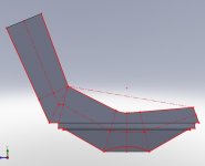
I want to be able to measure the cross sectional area of the throat, at different points in the horn path, including the volume of the driver and baffle that are usually accounted for by the Vtc and Atc figures.
I will then use the data to try and shape the throat to get a linear expansion throughout.
It’s going to take some number crunching and tweaking to get anything sensible. Then it has to be rationalised to take account of driver excursion, and timber construction, so I would rather start with some decent dimensional data for the driver.
Attached is a screen grab of what I think it might look like.
Regards Martin (Xoc1)
Look forward to seeing the results of your Othorn cabinets.
Hi TundraLTD.
Thanks for the Akabak Script. Very flexible and usable.
You mentioned that you measured your B&C 18SW115 driver. Any chance of posting the dimensions I requested. I don’t just want to calculate Vtc & Atc.
I want to be able to measure the cross sectional area of the throat, at different points in the horn path, including the volume of the driver and baffle that are usually accounted for by the Vtc and Atc figures.
I will then use the data to try and shape the throat to get a linear expansion throughout.
It’s going to take some number crunching and tweaking to get anything sensible. Then it has to be rationalised to take account of driver excursion, and timber construction, so I would rather start with some decent dimensional data for the driver.
Attached is a screen grab of what I think it might look like.
Regards Martin (Xoc1)
Attachments
Hi Martin,
In one of my SS15 improvement attempts for low end in single sheet thread of April last year I did something similar. At that time only TB46 seemed to be interested in my sharing of the cone volume compensation, lol
Edit: correction, it was March in post#597
In one of my SS15 improvement attempts for low end in single sheet thread of April last year I did something similar. At that time only TB46 seemed to be interested in my sharing of the cone volume compensation, lol
Edit: correction, it was March in post#597
...... If you worry about point A, it almost follows the outline of the driver's cone. You can see it as a driver volume correction (in both ways).....
Last edited:
Hi Xoc1,
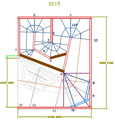
With your example in Post #523 you might be redesigning the throat and S1/S2 area into an enlarged throat chamber, that would be modelled more correctly as I'm showing in the attachment(?).
It may be more beneficial to stay with a small throat chamber with an adapter plate with an aperture that size-wise reflects S2.
Regards,
Attachments
Hi Josh
Look forward to seeing the results of your Othorn cabinets.
Hi TundraLTD.
Thanks for the Akabak Script. Very flexible and usable.
You mentioned that you measured your B&C 18SW115 driver. Any chance of posting the dimensions I requested. I don’t just want to calculate Vtc & Atc.
I want to be able to measure the cross sectional area of the throat, at different points in the horn path, including the volume of the driver and baffle that are usually accounted for by the Vtc and Atc figures.
I will then use the data to try and shape the throat to get a linear expansion throughout.
It’s going to take some number crunching and tweaking to get anything sensible. Then it has to be rationalised to take account of driver excursion, and timber construction, so I would rather start with some decent dimensional data for the driver.
Attached is a screen grab of what I think it might look like.
Regards Martin (Xoc1)
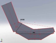
I've playing with Sketchup more today and it is giving me inconstant numbers on the volume calculation so I'm going to have to figure out whats up with that. But here is the basic model of the 18SW115 cone
I found an error in the Volume model this script has the corrected Vtc of 7873cc for a B&C 18SW115
COPY BELOW THIS LINE
|Rev5 - Model based on how geitmans built the spud script and now accounting for Vtc
|TH-18 Flat to 35hz! (Xoc1's design) on DiyAudio.com Collaborative effort
|I have not taken into account the bracing as it makes my head spin adding so many sections of script (I am working on it though)
|TundraLTD Enjoy!!
|=================================================================================================================================================================
|Network node numbers for this tapped horn system:
| 0-Voltage-1
| |
| -Chamber-5-Driver-------------------------------------------------------------------------------------------------------------
| | |
|8-Duct-9-Duct-10-Duct-11-Duct-12-Duct-13-Duct-14-Duct-15-Duct-16-Duct-17-Duct-18-Duct-19-Duct-20-Duct-21-Duct-22-Duct-23-Duct-24-Duct-25-Duct-26-Duct-27-Radiator
|=================================================================================================================================================================
Def_Const | Data for Vtc Chamber
{
Vtc = 7873.00e-6; |Throat chamber volume (cubic m)
Atc = 1210.00e-4; |Throat chamber cross-sectional area (sq m)
Sd = 1210.00e-4; |Diaphragm area (sq m)
Ltc = Vtc / Atc;
}
Def_Driver 'Driver'
|READ THIS
|Simply remove the block for the driver you wish to Sim
| <-block (in front of Sd) REMEMBER to only have one drive unblocked at a time
|18Sound 18LW2400-8
| Sd=1225.00cm2 Bl=25.77Tm Cms=1.07E-04m/N Rms=5.90Ns/m fs=35.0003Hz Le=1.35mH Re=5.00ohm ExpoLe=1
|B&C 18SW115-8
| Sd=1210.00cm2 Bl=28.31Tm Cms=1.21E-04m/N Rms=10.10Ns/m fs=30.9998Hz Le=1.70mH Re=5.10ohm ExpoLe=1
|B&C 18TBW100-8
| Sd=1210.00cm2 Bl=30.07Tm Cms=8.38E-05m/N Rms=6.78Ns/m fs=35.0003Hz Le=2.45mH Re=6.50ohm ExpoLe=1
|Precision Devices PD1850-8
| Sd=1150.00cm2 Bl=31.41Tm Cms=1.32E-04m/N Rms=6.65Ns/m fs=29.9999Hz Le=1.00mH Re=5.40ohm ExpoLe=1
|BMS 18N850v2-8
| Sd=1213.00cm2 Bl=25.11Tm Cms=1.18E-04m/N Rms=6.10Ns/m fs=29.7001Hz Le=0.89mH Re=5.00ohm ExpoLe=1
|Void Acoustics V18-1000-8
| Sd=1230.00cm2 Bl=34.96Tm Cms=9.35E-05m/N Rms=6.46Ns/m fs=34.5311Hz Le=2.20mH Re=5.50ohm ExpoLe=1
|18Sound 18NLW9600-8
| Sd=1134.00cm2 Bl=30.55Tm Cms=8.13E-05m/N Rms=6.62Ns/m fs=33.9997Hz Le=2.11mH Re=4.70ohm ExpoLe=1
System 'System 1'
Filter 'HighPass' |Highpass filter - 12dB Butterworth (change 'fo=***' and refresh for changes)
fo=31Hz vo=1
{b2=1;
a2=1; a1=1.414214; a0=1; }
Filter 'LowPass' |Lowpass filter - 48dB Butterworth (change 'fo=***' and refresh for changes)
fo=100Hz vo=1
{b0=1;
a8=1; a7=5.125831; a6=13.137071; a5=21.846151; a4=25.688356; a3=21.846151; a2=13.137071; a1=5.125831; a0=1; }
Driver Def='Driver'
Node=1=0=25=5
Duct 'Throat chamber' Node=5=9 SD={Atc} Len={Ltc} visc=1
Duct 'D1' Node=8=9 HD=53.5cm WD=5cm Len=21.92cm visc=50
Duct 'D2' Node=9=10 HD=53.5cm WD=8.6cm Len=19.23cm visc=50
Duct 'D3' Node=10=11 HD=53.5cm WD=11.8cm Len=6.75cm visc=50
Duct 'D4' Node=11=12 HD=53.5cm WD=10.4cm Len=24.92cm visc=1
Duct 'D5' Node=12=13 HD=53.5cm WD=12.1cm Len=10.6cm visc=1
Duct 'D6' Node=13=14 HD=53.5cm WD=12.9cm Len=11.5cm visc=1
Duct 'D7' Node=14=15 HD=53.5cm WD=13.8cm Len=15.17cm visc=1
Duct 'D8' Node=15=16 HD=53.5cm WD=14.9cm Len=9.35cm visc=1
Duct 'D9' Node=16=17 HD=53.5cm WD=15.5cm Len=9.54cm visc=1
Duct 'D10' Node=17=18 HD=53.5cm WD=16.2cm Len=8.6cm visc=1
Duct 'D11' Node=18=19 HD=53.5cm WD=16.8cm Len=11.72cm visc=1
Duct 'D12' Node=19=20 HD=53.5cm WD=17.6cm Len=15.21cm visc=1
Duct 'D13' Node=20=21 HD=53.5cm WD=18.7cm Len=16.42cm visc=1
Duct 'D14' Node=21=22 HD=53.5cm WD=19.9cm Len=49.74cm visc=1
Duct 'D15' Node=22=23 HD=53.5cm WD=23.4cm Len=10.26cm visc=1
Duct 'D16' Node=23=24 HD=53.5cm WD=26.9cm Len=11.11cm visc=1
Duct 'D17' Node=24=25 HD=53.5cm WD=29.6cm Len=28.49cm visc=20
Duct 'D18' Node=25=26 HD=53.5cm WD=40.9cm Len=28.49cm visc=1
Duct 'D19' Node=26=27 HD=53.5cm WD=50.8cm Len=19.93cm visc=1
Radiator 'R1' Def='D19' Node=27
Oliver,With your example in Post #523 you might be redesigning the throat and S1/S2 area into an enlarged throat chamber, that would be modelled more correctly as I'm showing in the attachment(?).
It may be more beneficial to stay with a small throat chamber with an adapter plate with an aperture that size-wise reflects S2.
If you simply do what is shown in your picture below, using 45 degree angles on the "V" centering on the cone with about a 3 inch flat spot in the center, your copy of the DSL design will be complete
.Art
Attachments
Oliver,Hi Art,
That's interesting, but those are Martin's pictures. Bye the way, I just find the tapped horn intersting, I was never out to duplicate or copy Danley's designs.
Regards,
Right, it was Martin who designed the copy
.Art
Djim,Art, if I listened careful to your words, I guess you just earned a complete firesquad…
Martin's plan was not a direct copy of the DSL TH-118 except the external dimensions and horn mouth, which still required "connecting the dots".
He figured out the last bit of "secret sauce" after examination of the cone control problem in his design.
Imitation is the sincerest form of flattery
.Art
Hi Art,
Usually it does but it this case I don't expect the cone volume correction will improve low frequency response. I also don't believe it will improve excursion stability since that is related to another problem. Fill the Xoc1 with a B&C 18SW115 and it will be stable. However, the cone correction could improve the response above 100Hz.
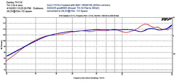
This is how your measurement and that of GS3525 integrate. Of course it stands or falls with the accuracy of the measurements. Nevertheless, it does similar in modelling so I don't expect huge differences. Also, at high power the 18NW100 is no competition to the 18SW115.
Usually it does but it this case I don't expect the cone volume correction will improve low frequency response. I also don't believe it will improve excursion stability since that is related to another problem. Fill the Xoc1 with a B&C 18SW115 and it will be stable. However, the cone correction could improve the response above 100Hz.
This is how your measurement and that of GS3525 integrate. Of course it stands or falls with the accuracy of the measurements. Nevertheless, it does similar in modelling so I don't expect huge differences. Also, at high power the 18NW100 is no competition to the 18SW115
.
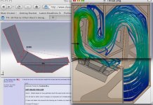
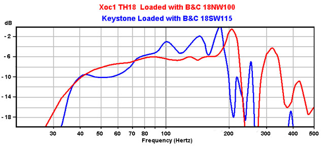
Playing with Akabak more this evening I tried making the baffle opening smaller which would help in equalizing the pressure across the surface of the cone. It also looks to smooth the response, which is more evident in upper frequencies similar to DSL graphs. I'm going to build mine with a 22.8cm or 9" opening centered on the driver unless anyone can explain why this would be a bad idea? You can close the opening down to 28cm (11") without affecting the the response at all!
This applies to the B&C 18SW115, other drivers may vary a bit
This applies to the B&C 18SW115, other drivers may vary a bit
To be internally consistent within the Keystone thread, I chose to use the charts using a cheap (bought used) RTA 420 microphone at 2 meters for all the posts.Hi Art,
Fill the Xoc1 with a B&C 18SW115 and it will be stable. However, the cone correction could improve the response above 100Hz.
This is how your measurement and that of GS3525 integrate. Of course it stands or falls with the accuracy of the measurements.
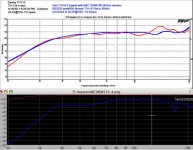
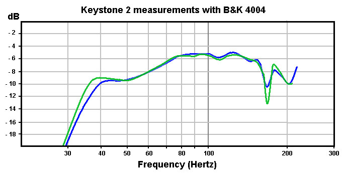
Below is the Keystone measured with a much better microphone, a B&K 4004. Unfortunately, the measurement distance was not noted, but since the upper response is different, it probably was not at 2 meters.
The same trace has also been included with smoothing similar to what DSL uses, the trace in the left hand picture has no smoothing.
It is apparent the Keystone SPL drops off more rapidly below 35 Hz than the DSL TH-118 or the Xoc1 TH18.
Whether the Keystone's extra cabinet volume, 25% larger frontal area and different tuning approach result in it having more or less output at 40 Hz could only be determined if all three cabinet test set ups were identical.
At any rate, the difference between the cabinets does not appear to be much, other than shape and cone control.
The Keystone is 5 inches taller, 4" wider, and 6" more shallow than the other cabinets, which works better for my PA needs.
Art Welter
Attachments
Hi Art,Whether the Keystone's extra cabinet volume, 25% larger frontal area and different tuning approach result in it having more or less output at 40 Hz could only be determined if all three cabinet test set ups were identical.
I don't think a 25% larger reflective front in advantage of the Keystone is large enough to make its Fb drop or show significant increase of the SPL at 10m. The effect of reflective panels/front is limited by its 1/4WL.
I have studied your B&K measurements and I see a 3HZ drop of the Fb in the left plot (see picture below). The right one is close the measurement with the cheaper mic so I guess the left B&K measurement is from very close range or maybe measured with a second Keystone next to it, I don't know.
When I line up the right measurement of the B&K 4004 with the Xoc1-TH18, they are looking quiet close indeed.
It looks like that the Keystone, Xoc1-TH18 and Danley's DSL TH118 are all very close in system volume and response. In other words, the way of folding or changing the shape of the mouth are of relative influence on the subrange response.
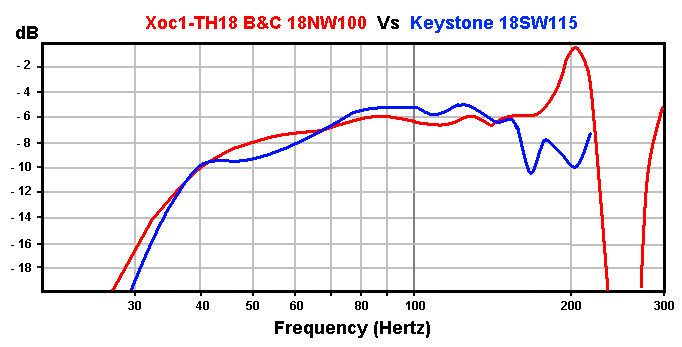
It looks like that the Keystone, Xoc1-TH18 and Danley's DSL TH118 are all very close in system volume and response. In other words, the way of folding or changing the shape of the mouth are of relative influence on the subrange response.
Both left and right are the same measurement, the right plot is smoothed, which distorts the LF knee point, making it look softer than it is, which looks like less LF. The left response is correct.Hi Art,
I don't think a 25% larger reflective front in advantage of the Keystone is large enough to make its Fb drop or show significant increase of the SPL at 10m. The effect of reflective panels/front is limited by its 1/4WL.
I have studied your B&K measurements and I see a 3HZ drop of the Fb in the left plot (see picture below). The right one is close the measurement with the cheaper mic so I guess the left B&K measurement is from very close range or maybe measured with a second Keystone next to it, I don't know.
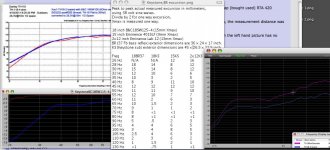
A larger frontal area definitely makes a difference all the way down to Fb, as shown in the tests shown on the right of the graphs below. The extender, with about a 50% increase in frontal area increases level by 3 dB or more. The larger frontal area does not decrease F3, but increases forward directivity, increasing level down to Fb.
One difference in the Keystone compared to the XOC1 and DSL design is it has a slightly lower tuning, about 34 Hz Fb (compared to about 38 Hz). That can be seen in the actual (measured) excursion measurements below.
The Keystone stays "on the pipe" a little lower, but unloads more rapidly below Fb.
The narrow "Q" of the TH tuning is apparent compared to a BR.
The 15" had much more narrow tuning peaks than the 18" or dual 12" (even after closing the mouth to get a reasonably flat response), the phase/group delay problems the tuning peaks cause may have been what I heard as objectionable in sound quality even more than the cone distortion.
It would be interesting to see measurements of the Xoc1 TH18 excursion, excursion shows the "Q" of the tuning more clearly than impedance plots do.
Art
Attachments
Last edited:
- Home
- Loudspeakers
- Subwoofers
- TH-18 Flat to 35hz! (Xoc1's design)