One thing with tapped horn orientation in room..
I never got my tall narrow 15" driver tapped horns to work their best with them facing towards the listening chair.
Turning them 90 degrees, so the output opening faced each other across the room, always measured and sounded better as a pair like that.
They are time aligned.
This was so in my old 6.5m X 5m room, also at a huge hotel conference room I showed them at the same, that was some 80 or 90sqm or more
In my current loft room, at first I struggled to get good sub bass acoustics. Tried them down the room, across, the openings farthest away / nearest - eventually firing them upwards, farthest away (they are laying down, worked just fine..
Flexibility was good for my rooms.
Ok so single sub or dual sub stacked with room eq is preferred over 2 different location trying to create a sweet spot with room eq (even if distance to mlp is the same).
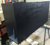
My plan is to position them behind the couch against the wall in a opright position to reduce footprint.
Option nr. 2 is to place them horizontally against the back wall with the ports facing eachother and put my rear surrounds on them. Ports need to be one the "bottom" though. Thats a minor adjustment however.
Below 60Hz it doesn't really matter if the subs are at the front or the back right? Unless you have a really deep room I guess.
I think that applying to configurable ports on this sub is the best option. Than I have some flexability. Little bit of router action needed.
Then it is settled. A combination of the top left in the sketch and the one in the picture.
I think that applying to configurable ports on this sub is the best option. Than I have some flexability. Little bit of router action needed.
Then it is settled. A combination of the top left in the sketch and the one in the picture.
Attachments
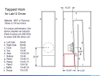
A quick napkin calculation tells me that the surface area of the mount will be reduced by roughly 6% and that's with stretching the height a little bit (the red mod). Will this have a big affect?
And is it possible to load this thing up with 2 woofers by removing panel k?
And is it possible to load this thing up with 2 woofers by removing panel k?
Attachments
Last edited:
A more precies calculation shows it's around 3% less area but by making the port 1 cm taller it's more or less the same.
After doing some imaginary redecorating I came to the conclusion that 2 of these subs would barely fit against the back wall horizontally. Who needs a diningtable anyway?
So I still would like to know if 2 woofers could be an option or does that require a total remoddeling? Can someone share a hornresp model/export file for that please?
One thing with tapped horn orientation in room..
I never got my tall narrow 15" driver tapped horns to work their best with them facing towards the listening chair.
Turning them 90 degrees, so the output opening faced each other across the room, always measured and sounded better as a pair like that.
They are time aligned.
Works both ways 4 me!
No reason to not match the original opening area, but a 6% increase or decrease would have little to no effect in the range you are using it.A quick napkin calculation tells me that the surface area of the mount will be reduced by roughly 6% and that's with stretching the height a little bit (the red mod). Will this have a big affect?
Reduction in the opening size tunes lower and reduces sensitivity, larger tunes higher and louder.
The distance of the opening to any boundary (floor, wall, ceiling) will have an effect.
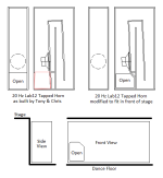
Since you are already planning for two mouth exit options, a third opposite of the new red mouth would allow for symmetrical coupling. The boundary area increase of two 30"x60" panels may have as much as a 3dB increase in output.
Alternatively, locating the mouth exits by each wall may be preferable, or one mouth up, one down to break up symmetrical room modes.
For most rooms, the side exit locations would be preferable to a front location both acoustically and aesthetically.
And is it possible to load this thing up with 2 woofers by removing panel k?
The center of the two drivers should be at the center of the single driver, panel "K" moved down to just below the lower driver.
Your Hornresp models simply needs the number of drivers changed to "2" in the field labled "TH", choose series or parralel.
Depending on your amps, you may want to use 8ohm versions of the drivers if available, which have slightly different TS parameters to load in to the other fields
Use plenty of bracing, the cabinet will have 6dB more vibration potential.
Have fun with the build!
Art
Last edited:
Already was planning on "mirroring" them for that exact purpose. However I meant 2 subs with one woofer or a single sub with two woofers. In case of the latter it wil be in series to have a 8 ohm load. My amp has bridge mode but only for 8 ohm operation, roughly 250 watts continuous.
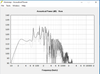
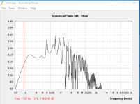
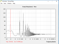
Ok some sims. I'm not impressed with the low end. Pretty much stays the same. Maybe because needs larger horn with two driver? I'm sticking with 2 single 12'''s. More versatility and having +-3dB advantage across the entire bandwidth when coupling right? Freq response is a lot nicer disregarding the low end part. GD is way better too. Is there a way to make it shift to the left a little bit. Having that bump at 20Hz for example.
Attachments
Last edited:
My 15" modelled similarity.
Bit more energy at 20Hz though.
Was not as efficient at 105 to 107dB but they keep up with the rest just fine.
In reality if there's something at 20Hz being played, it makes its presence felt - big time!
One church organ piece shows flat level energy at 18Hz!
You just feel it..
Perhaps that's a room thing here.
I have to have a -10dB PEQ cut at 30Hz because of a massive room mode. Apart from that no other correction needed.
Have you modelled with longer horn path?
I'm totally new to hornresp and th. That's why I asked for help. Is it possible to remove panel "k" and place both woofers at a lower position thus increasing the horn length a tiny bit? Or to put it differently, remove "k" and place the second woofer there. Exact position yet to be determined.
Doubling the cabinets and power nets a 6dB gain. To bump up the low end with this driver would require a larger cabinet.Ok some sims. I'm not impressed with the low end. Pretty much stays the same. Maybe because needs larger horn with two driver? I'm sticking with 2 single 12'''s. More versatility and having +-3dB advantage across the entire bandwidth when coupling right?
I'm guessing your sim is no where near Xmax, if you used more power you could equalize the low end flat.Freq response is a lot nicer disregarding the low end part. GD is way better too.
The gain seen in the 20-40 Hz range is the equivalent of over twice as loud. There is not much music content down below 25Hz, and some compression/clipping on LF effects below that may keep the room's drywall in place.
That said, you should test your room with a speaker in the location where the horn exit can be put to see what the room does to the response before deciding what the speaker response should look like.
The TC Sounds Epic 12 puts the bump at 20Hz, but drivers like that cost more than power ;Is there a way to make it shift to the left a little bit. Having that bump at 20Hz for example.
The design was tweaked for the smoothest response, moving the driver center closer to the mouth would probably screw up the response and not gain much, if any low end. Try lengthening S1 and shortening S4 to see the effect, you may have to tweak S2/S3 a bit if the volume changes by more than several liters.Is it possible to remove panel "k" and place both woofers at a lower position thus increasing the horn length a tiny bit? Or to put it differently, remove "k" and place the second woofer there. Exact position yet to be determined.
Just noticed the VTC and ATC are set to zero, there is a few liters in the cone (volume of throat chamber) around S1, and the driver(s) reduce the volume near the mouth, but what the hey..
Your room modes are probably going to be doing really nasty things to any sub you go with.
Personally, once I have a respectable design (not perfect - cos there's no such thing really) it's time to get building - planning paralysis beware.
The key ultimately is an ability to measure where in your room your sub(s) should go to minimise modal interaction AND having adequate EQ to pull down any modes that you are left with.
Integration is paramount and this guide explains it all really well:
Red Spade Audio: Bass integration guide
@Magician1981
You can assuming they will fit, though recommend with the top one inverted. Note too that in removing 'k' and adding a driver its CR ~ doubles on average, so with cheap drivers, it might be best to adjust each panel slope to account for ~ maintaining its original design CR as I'm not sure even the best prosound subs can handle > ~3:1 at anywhere near Xmax.With 20V single driver and 40V dual driver the cone reaches 10mm which is the linear one way xmax given by alpine.
No drywalls here in the Netherlands. Concrete, bricks and thick gypsum blocks")
The tc sound isn't available over here nor afforable as you hinted.
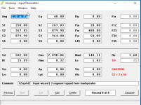
Some parameters in the screen I posted where incomplete. In my other screens I use ap=40, lpt=4 as they where mentioned a few pages back (#136). What's the general rule of thumb regarding atc and vtc? 2500 and 500?
No drywalls here in the Netherlands. Concrete, bricks and thick gypsum blocks
The tc sound isn't available over here nor afforable as you hinted.
Some parameters in the screen I posted where incomplete. In my other screens I use ap=40, lpt=4 as they where mentioned a few pages back (#136). What's the general rule of thumb regarding atc and vtc? 2500 and 500?
Last edited:
- Home
- Loudspeakers
- Subwoofers
- Lab12 - Tapped Horn