If you come back down from 15" drivers to 12"', you'll find that the Exodus Shiva-X2 can be built in a ported enclosure as small as 70 litres. Shiva-X2 Application Notes - Home Theater Systems - Electronics and Forum - HomeTheaterShack
Thanks for that tip, it models really nicely, however it's a bit on the pricey side, and not entirely easy to find around here.
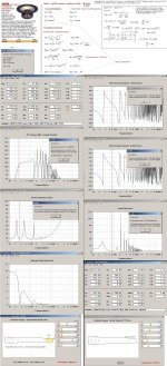
But silly me, I spent so much time looking at the Dayton DVC-385 15", I didn't look at the DVC-310 12" little brother at all.
Apart from lower power handling and xmax, it does appear to be rather similar to the Shiva X-2, apart from 2Hz higher F3 in this application:
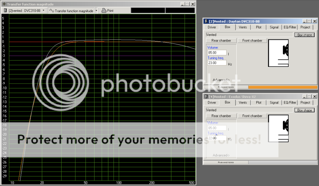
(pic is with subsonic 24dB filter)
Seems to work quite nicely in a 85l vented box (my size limit) and a 24Hz -3dB point is quite nice in my opinion.
At 139$ from PE, that's just under 100€, and I think I could get it over here for an additional 50 euros. Add 250 for this amp and I'm only over my budget by the material cost.
arande2, I also looked at the XLS/XXLS, but not sure they're what I'm after.... will look at the Seas link tomorrow as well, thanks The golden mean.
Meanwhile, any opinions on the 85 liter box with the Dayton 12"?
The Reckhorn amp is probably a good product. For the project for my friend we will go for
the XTZ amp tested in Klang+Ton 4/2009. It would have been interesting to compare the two amps but Reckhorn isn´t being sold in our country I believe.
Resultat av Googles bildsökning efter http://www.mindaudio.de/picture/kundenpics/Sheet_SubAmp1/SubAmp1_panel_detail.jpg
the XTZ amp tested in Klang+Ton 4/2009. It would have been interesting to compare the two amps but Reckhorn isn´t being sold in our country I believe.
Resultat av Googles bildsökning efter http://www.mindaudio.de/picture/kundenpics/Sheet_SubAmp1/SubAmp1_panel_detail.jpg
Have a look at the maximum SPL graph, that's where the differences between these drivers will show up. You should find that the maximum SPL at F3 of the Shiva is much higher than the Dayton.
That said, the Dayton is still a good driver, and much cheaper.
The cheapest place to get the exodus gear in Europe is (usually, depending on the exchange rate) at Shiva-X2 12" , prices are inclusive of shipping.
That said, the Dayton is still a good driver, and much cheaper.
The cheapest place to get the exodus gear in Europe is (usually, depending on the exchange rate) at Shiva-X2 12" , prices are inclusive of shipping.
The Reckhorn amp is probably a good product. For the project for my friend we will go for
the XTZ amp tested in Klang+Ton 4/2009. It would have been interesting to compare the two amps but Reckhorn isn´t being sold in our country I believe.
Hello,
it's a bit hard to find much feedback on either amp, I did find a little bit on the Reckhorn, though some of it was for older versions (400-402). Some criticisms, but most of them seem to be issues that have been rectified or are easily rectified. Germany offers a 14 day return law for online purchases, so should I be somehow discontent I can utilize that.
It's nearly impossible to find any mention of "sound quality", but I assume when you're looking at the amp of the woofer, there's not too much effect on the total tonal quality of your system.
In fact, an idea I had was to just build the enclosure with driver, and amplify it with one of the rear surround channels on my 7 ch amp. the input signal would already be highpassed, and I did some checks with WinISD Pro, 60Watts of amplification would keep the excursion below xmax, even in the subsonic range without a low cut, and would still go plenty loud enough for my taste.
Have a look at the maximum SPL graph, that's where the differences between these drivers will show up. You should find that the maximum SPL at F3 of the Shiva is much higher than the Dayton.
That said, the Dayton is still a good driver, and much cheaper.
The cheapest place to get the exodus gear in Europe is (usually, depending on the exchange rate) at Shiva-X2 12" , prices are inclusive of shipping.
Thanks, that is rather pricey. Thanks for the info about SPL, but I think that's not something I need to be worried about, seeing as I'll be using this in a 24 m^3 (yes, that's a 3!) room at first.
On a slightly unrelated note - the fact that parts-express.com has been unreachable for nearly a week now is quite annoying, and hinders my research a bit.
In fact, an idea I had was to just build the enclosure with driver, and amplify it with one of the rear surround channels on my 7 ch amp. the input signal would already be highpassed, and I did some checks with WinISD Pro, 60Watts of amplification would keep the excursion below xmax, even in the subsonic range without a low cut, and would still go plenty loud enough for my taste.
If its not too expensive, I'd go with a big amp for the sub, music with a higher peak-to-RMS ratio than sinewave (only 3dB) require more headroom. The point is not to blast 500W or whatever continuously when playing loud, but to avoid clipping due to voltage (or possibly current) limiting at the amplifier.
If you're curious about Peerless XLS/XXLS performance, here are measurements of one 85L ported XLS 12" DIY Peerless XLS 12" ported 85L - Home Theater Systems - Electronics and Forum - HomeTheaterShack
That's very solid distortion performance, among the very best and ultimately limited by the amplifier in this case.
This smaller passive radiator build fares well too until the even smaller amp runs out of gas: DIY Chorus XP3 clone - Home Theater Systems - Electronics and Forum - HomeTheaterShack
If you can source the Dayton RSS-series drivers, they are very good performers too. Diymobilaudio forum hosts some Klippel tests of drivers, here's a test of the 12" Dayton RSS315HF: DIY Mobile Audio
I would expect that Dayton to perform as well as the XLS/XXLS-line from Peerless.
I recently measured my Dayton RSS390HF in a similar (but not exactly the same) manner to the above HTShack tests. I used a very small sealed box which requires external EQ for good in-room balance, but distortion performance per SPL remains quite good; a testament to the good design of the RSS-series.
A larger box would allow less steep roll-off, but I think on balance those 12" ported/PR builds based on RSS, XLS or Shiva-X are better with box sizes in the 80L range.
If its not too expensive, I'd go with a big amp for the sub, music with a higher peak-to-RMS ratio than sinewave (only 3dB) require more headroom. The point is not to blast 500W or whatever continuously when playing loud, but to avoid clipping due to voltage (or possibly current) limiting at the amplifier.
How big is big? My mention of the 60Watts of amplification was just sort of as a stop-gap, temporary measure, to get an idea of the extended frequency range of a subwoofer, before I buy a proper sub amp. The reckhorn is rated at 290W into 4Ω, though I could probably even find a more powerful amp.
However, I once read that it's recommended to have an amp with less power than the driver's Pe, so that you don't push more power into the driver than it can handle. Or am I confusing something here? It was a while ago that I read that.
If you're curious about Peerless XLS/XXLS performance, here are measurements of one 85L ported XLS 12" DIY Peerless XLS 12" ported 85L - Home Theater Systems - Electronics and Forum - HomeTheaterShack
That's very solid distortion performance, among the very best and ultimately limited by the amplifier in this case.
This smaller passive radiator build fares well too until the even smaller amp runs out of gas: DIY Chorus XP3 clone - Home Theater Systems - Electronics and Forum - HomeTheaterShack
Thanks for the HTS links, it seems to be a good resource.
If you can source the Dayton RSS-series drivers, they are very good performers too. Diymobilaudio forum hosts some Klippel tests of drivers, here's a test of the 12" Dayton RSS315HF: DIY Mobile Audio
I would expect that Dayton to perform as well as the XLS/XXLS-line from Peerless.
They are a bit more expensive to ship due to their higher weight, but I should be able to get ahold of them as well. I was recently reading about the RSS315, because Zaph designed a sub using that, which is a pretty good recommendation in itself for me.
I unfortunately can't view the link, because it wants me to sign up / log in first - is the data worth registering for? I'm a bit reluctant to sign up to a ton of places...
")
A larger box would allow less steep roll-off, but I think on balance those 12" ported/PR builds based on RSS, XLS or Shiva-X are better with box sizes in the 80L range.
That's relieving, cause I can't fit anything larger than 90L or so
I think I've discovered a few good drivers / designs already, not too easy to chose one. However I'm definitely still going to do some more research before I build - hopefully I will find something so good that the choice is made easy
One question: It seems like most sub amps have a subsonic lowcut filter, which is necessary for vented designs. Are there also amps without that filter? It seems to me that it would be quite unnecessary in a sealed design, and would only add group delay but no real benefit - is that correct?
I was pretty set on building a vented sub based on the WinISD models, but having seen some in room response curves of sealed subs, and also what can be done with EQ and linkwitz circuits, I'm not so sure anymore...
Last edited:
if you want to get the maximum clean (unclipped) SPL from a speaker it seems to be generally advised to use an amplifier that is capable of delivering double the power rating of the speaker.
For domestic listening this max SPL requirement is nonsense.
I modified a B950 by doubling the mass of the cones, thus reducing the sensitivity by 6dB and retuning the ports down by half an octave.
The speaker now does 95dB/2.83V @ 1m and is rated for amplifiers between 1000W into 4ohms to 2000W into 4ohms.
I am using just 340W into 4ohms and it produces generous bass, that sounds just right for all programme material, with just a few tenths of a watt driving it.
The amp and speaker have a +30dB transient capability if something louder comes along at those low frequencies.
The ratio of amp power to speaker power is debatable. Too little amp power, it clips, speaker dies due to excess square waves, resulting in extra (free, in the form of short-term DC) power being shoved in.
At roughly 1:1, the speaker hits mechanical limits as the amp starts to clip - very nasty sound very quickly.
More (significantly more) power from the amp means the speaker will go into mechanical damage, and the voicecoil will need replacement due to it hitting the backplate. This would only happen when excursion becomes an issue. For mids/highs, it's probably best to use too much power.
IMO, see what you can get hold of, make sure the price is right. But make sure it is ENOUGH power - you don't want the amp to clip at 90dB.
Chris
Well, I'm back with a concept. I'd been thinking about doing dual Dayton RSS315HFs in 60 liter cubes (each external edge 450 mm / 18 inches long). However, seeing as I have a very small room (10 square meters / 110 square feet), two concerns need to be addressed. One is obvious: lack of space. I'd like to have as small a footprint as possible, and each of those boxes would eat away 0.2 square meters of my precious 10. The other concern is room modes and standing waves. The reason I've been looking at dual subs is not for more output, but rather because I heard placing 2 subs at opposite ends of the room helps alleviate room modes.
So, I had an idea, which would kill two birds with one stone. Introducing... The Monolith:
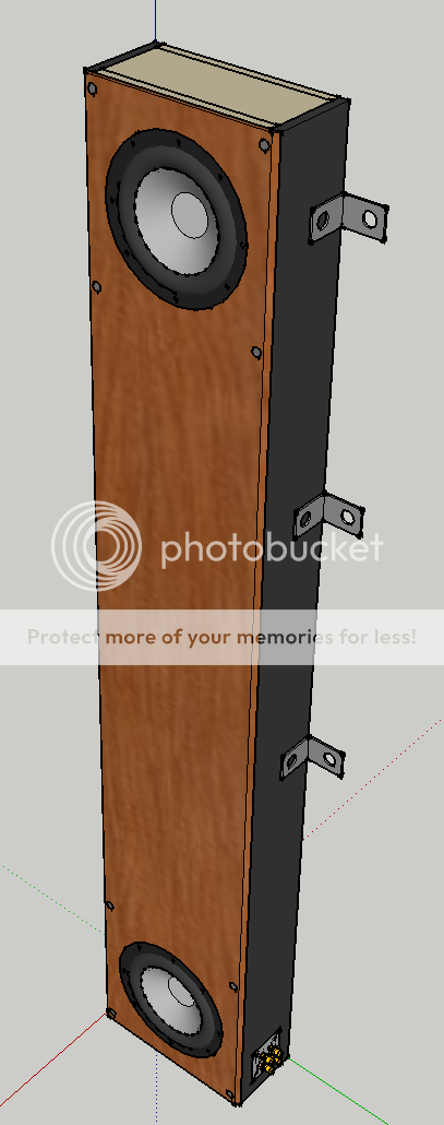
What do you think? It's basically two 60 liter subs in one enclosure (separated from each other by an MDF divider). Its external footprint is a mere 190mm x 420mm (7.5" x 16.5") and it's 2.4m tall (8ft), meaning it would span the entire height of the room, placing one driver near the floor, and one near the ceiling.
Here's a few more schematics I made:
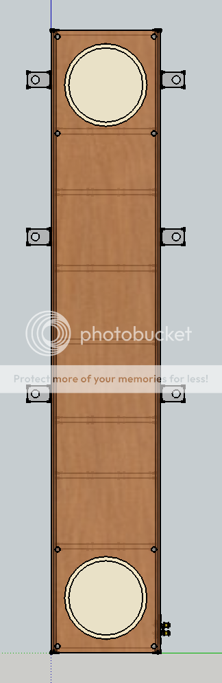
Front view:
Top view:
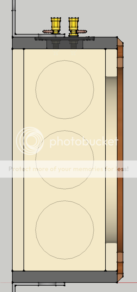
Side view:
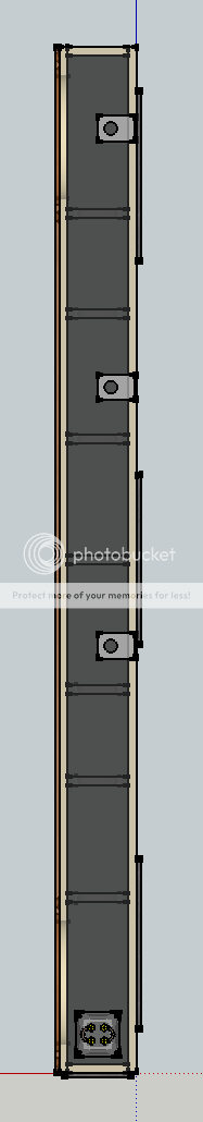
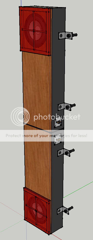
3D view:
(one thing not visible on the 3d view yet, which I just added, is that I decided the divider between the 2 compartments should be sturdier - brace construction shamelessly stolen from Zaph)
(also, the z-axis placement of the braces is far from decided, in fact I just put them in randomly in sketch-up - in a final build the plan would be to have them spaced at indivisible distances, or perhaps multiples of the golden ratio, as to minimize vibrations)
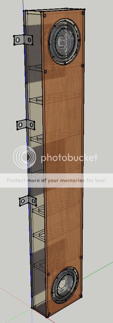
The construction I'm imagining would be quite simple, using mainly 19mm thick MDF, just (4) 8-foot-long rectangles to make the sides of a long box, and (9) little 142mm x 382mm rectangles would serve as the floor, ceiling, divider and braces of the box.
Add in an 8ft long piece of 10mm thick solid wood or plywood glued to the front, serving both the purpose of making it look better, and eliminating the need to recess the drivers. And it would hold the magnets for attaching the grilles (a simple canvas spanned pine-beam frame)
Amplification would be external of course, with dual terminals to allow for series / parallel / "bi-amping" connection.
As you can see, it would have metal L-joiners (not sure what the proper term for these is) attached to the side, to mount it to the wall to keep from falling over (when the bass is booming ). Between the box and the wall/floor would be slabs of rubber/bitumen "washing machine decoupling mats", which are available cheaply at home improvement stores.
No worries about the wall rattling, by the way, as it's a solid concrete behemoth which is very rigid and solid even by thorough German construction standards.
So, what do you think? I've spent some time thinking this through, but I can't really catch issues of which I'm not aware that they exist.
Does this look like a good idea? I rather like the thought of it, because it would be nice and unobtrusive I think (despite it's rather massive size). Am I missing something?
Any feedback is appreciated, Thank you.
So, I had an idea, which would kill two birds with one stone. Introducing... The Monolith:
What do you think? It's basically two 60 liter subs in one enclosure (separated from each other by an MDF divider). Its external footprint is a mere 190mm x 420mm (7.5" x 16.5") and it's 2.4m tall (8ft), meaning it would span the entire height of the room, placing one driver near the floor, and one near the ceiling.
Here's a few more schematics I made:
Front view:
Top view:
Side view:
3D view:
(one thing not visible on the 3d view yet, which I just added, is that I decided the divider between the 2 compartments should be sturdier - brace construction shamelessly stolen from Zaph)
(also, the z-axis placement of the braces is far from decided, in fact I just put them in randomly in sketch-up - in a final build the plan would be to have them spaced at indivisible distances, or perhaps multiples of the golden ratio, as to minimize vibrations)
The construction I'm imagining would be quite simple, using mainly 19mm thick MDF, just (4) 8-foot-long rectangles to make the sides of a long box, and (9) little 142mm x 382mm rectangles would serve as the floor, ceiling, divider and braces of the box.
Add in an 8ft long piece of 10mm thick solid wood or plywood glued to the front, serving both the purpose of making it look better, and eliminating the need to recess the drivers. And it would hold the magnets for attaching the grilles (a simple canvas spanned pine-beam frame)
Amplification would be external of course, with dual terminals to allow for series / parallel / "bi-amping" connection.
As you can see, it would have metal L-joiners (not sure what the proper term for these is) attached to the side, to mount it to the wall to keep from falling over (when the bass is booming
). Between the box and the wall/floor would be slabs of rubber/bitumen "washing machine decoupling mats", which are available cheaply at home improvement stores.No worries about the wall rattling, by the way, as it's a solid concrete behemoth which is very rigid and solid even by thorough German construction standards.
So, what do you think? I've spent some time thinking this through, but I can't really catch issues of which I'm not aware that they exist.
Does this look like a good idea? I rather like the thought of it, because it would be nice and unobtrusive I think (despite it's rather massive size). Am I missing something?
Any feedback is appreciated, Thank you.
Last edited:
When it comes to flexability two separate enclosures is better I think. You can calculare the modes for your small room and in some way predict the best place to locate them. You probably know of programs like Cara. But moving them around some is as I see it the final touch. There is the possibility that let´s say four smaller subs would give an even better end result but then we have a more complex solution.
I´ve seen mesurments for six subs placed differently in one room and some may say when it comes to so many there is only the option of placeing them in a random way.
I´do not doubt that your plan will work. But there are the rather large areas of the front and back panel. They are at risk of vibrating. The bracing and the tight connection of the back panel to the wall may cure this but I would like to see some combinations of different materials because the different properties of materials can aid in rejecting vibrations (we may call it acoustic impedances). It can be as "easy" as bonding MDF and particle board together, or more advanced; granite and plywood or slate and plywood. Braces in different directions and in a more irregular pattern is what I have used. I believe modern CAD programs may fool us to make nice and symmetrical drawings but this may not be the best approach in the real world.
When it comes to flexability two separate enclosures is better I think.
I think you are correct. I was doing some FR measurements, and some room mode experiments, and was quite horrified with what I found. The more options I have to fix this horrid acoustic mess, the better.
I've heard of Cara, but never tried it, as it isn't freeware, and I'm not much of a software-buyer. I would imagine that software modeling quickly runs into its limits when modeling such a complex system, and it's easier just to try stuff out.
There is the possibility that let´s say four smaller subs would give an even better end result but then we have a more complex solution.
I´ve seen mesurments for six subs placed differently in one room and some may say when it comes to so many there is only the option of placeing them in a random way.
While I've no doubt this is a possibility, there is a point when I need to let practicality take over. When I say my room is 10 square meters, I do not mean that I have a listening room which is 10 square meters, and that contains nothing but a small sofa and two speakers. No - I wish that were the case, however it is not. These 10 square meters are my listening room, my living room, my movie room, my bedroom, my work room and my dining room - all at the same time. If you like, you can get an idea of how tight it is from this floor plan. As you can see the southern wall is still more or less free, which is why I was hoping for something I could place there.
But, you definitely got me thinking about separate enclosures. Which brings me to v1.1, the stack:
Instead of one monolith, simply use 2 half-monoliths stacked on top of each other, with the same damping material as is already in use against the wall between the two enclosures. This was actually my very first idea, which I rejected in fear of the top one falling off. But if it's gonna be screwed to the wall anyway? Why not.
If the tower setup works, then all's good and well. and if not, the unusual form factor should allow me a few creative placement options: under my bed, behind my desk, in my closet (?), and even allow for the option of raising the woofer 80cm by doing nothing other than simply turning the cabinet upside down.
Added bonus - a 120cm long cabinet ought to fit into every car - I can't always count on my parents' Volvo being at my disposal
I´do not doubt that your plan will work. But there are the rather large areas of the front and back panel. They are at risk of vibrating. The bracing and the tight connection of the back panel to the wall may cure this but I would like to see some combinations of different materials because the different properties of materials can aid in rejecting vibrations (we may call it acoustic impedances). It can be as "easy" as bonding MDF and particle board together, or more advanced; granite and plywood or slate and plywood. Braces in different directions and in a more irregular pattern is what I have used. I believe modern CAD programs may fool us to make nice and symmetrical drawings but this may not be the best approach in the real world.
As for the reduction of vibration - I think the combination of 2 different types of irregular bracing, the layer style MDF & hard-/plywood baffle and the wall mounting will do a good enough job keeping it fairly low. I believe it should probably be rather insignificant compared to the elephant in the room - room acoustics. Should I ever move to a place with different space requirements I can always build a new enclosure - it's not like there's much to do other than unscrew and re-screw the woofer and jam the binding posts through.
There is the possibility that let´s say four smaller subs would give an even better end result but then we have a more complex solution.
While I've no doubt this is a possibility, there is a point when I need to let practicality take over.
Looks like I'm going to have to eat my own words.
I got myself this:

But oh wait, what the **** is that? Let's look around the side....

Damn, stupid USPS, and stupid MCM doing a crappy job packing.
Let's open up and see how it looks inside....
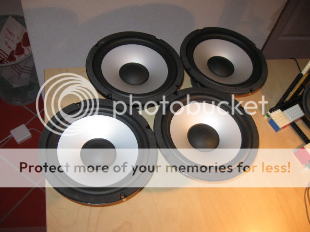
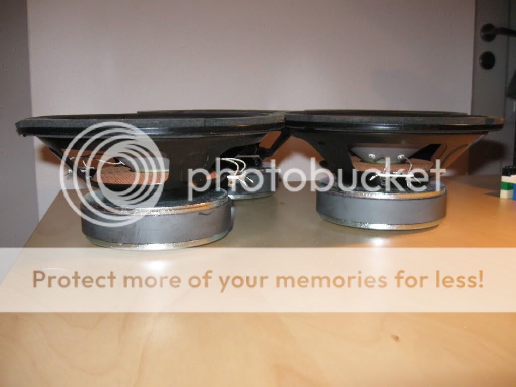
As it turns out, 3 out of four of the frames are bent, two of them slightly, one of them bent to hell.
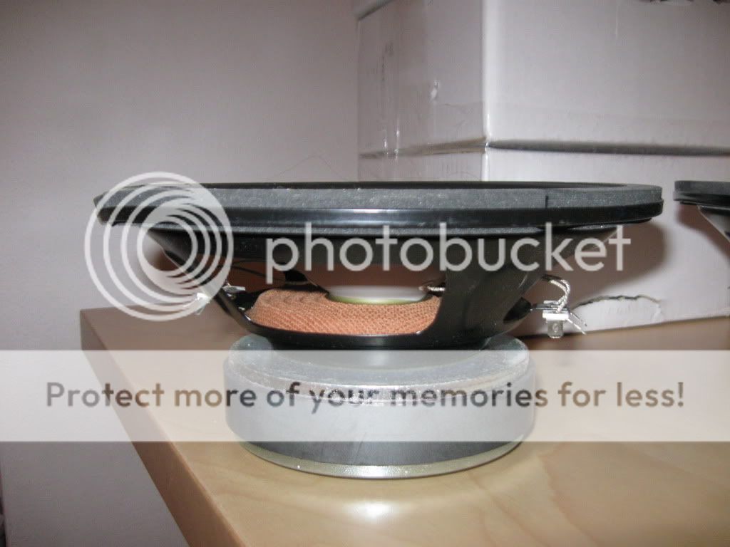
Only one of the drivers I can stand face down on the desk without it wobbling.
So I need your advice guys. These drivers are from USA, and are in Germany right now. It would be a major pain in the *** to return them.
Does a bent frame affect the operation of the woofer? If I try to bend them back myself using some pliers, will they work perfectly afterwards? Or has permanent damage already been done / would it occur during bending back?
What do you think I should do? Do I need to send them back, or should I try repairing them myself?
Question two:
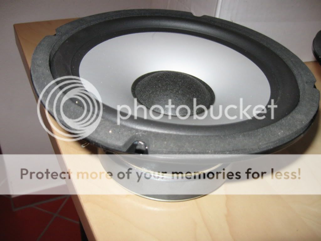
The woofers are MCM 55-2185s. Specs can be found by clicking the link.
What kind of enclosure should I build? My windows desktop computer died today (yeah, I'm kind of having a sh--ty day - bent woofers & broken motherboard), but before it died I did some WinISD Pro simulations.
I don't remember the exact details, but I was looking at putting the woofer into a 34l (1.2 cu ft) enclosure, one woofer per box, so four boxes. The boxes would be vented, and tuned to somewhat below the Fs, for an slight upwards slope (ie, a bit quieter at lower freqs) probably to somewhere in the range of 25Hz, and using equalisation and room gain to flatten the FR out.
Out of all the things WinISD simulates (sealed, vented, bp, isobaric) that seems like the best option. But what about all the other types of subwoofer enclosures? There are things like tapped horns, quarter wave tubes, front and rear horns, transmission lines, etc etc. I know little about any of these types of enclosures, and I don't know how to simulate them. Can anybody tell me if there is any type of enclosure that might be better for these woofers than vented? They don't have very much xmax, but I'm not aiming for very high SPLs.
Last edited:
Interesting project, I look forward to seeing how the 4 seperate subs work out when positioned, I've heard good things about this principle
Shame about the damage to those drivers, very poor really. First check the voice coils don't rub by pushing the cone down gently and evenly. If they move smoothly you may consider reforming the basket.
I'd basically mount them to a scrap baffle to reform them perfectly flat. Screws through the mounting holes alone may not be sufficient or even enough pressure to refrom the baskets though. I'd prepare one sturdy baffle with a driver cutout hole and find another suitable flat and sturdy board to press down on the woofers cardboard mounting ring part. Hopefully it'll push flat and stay flat afterwards, but I do not have first hand experience of this.
WRT enclosures, the tapped horns, quarter wave tubes, front and rear horns and transmission line types are likely to be a great deal larger than a ported box, so may not be as suitable for you.
Thanks, I'm looking forward too.Interesting project, I look forward to seeing how the 4 seperate subs work out when positioned, I've heard good things about this principle
It doesn't feel like anything is rubbing, can't hear anything rub. I will be contacting MCM about some kind of discount if I keep them, or about exchanging them. Let's see what we can work out.Shame about the damage to those drivers, very poor really. First check the voice coils don't rub by pushing the cone down gently and evenly. If they move smoothly you may consider reforming the basket.
I'd basically mount them to a scrap baffle to reform them perfectly flat. Screws through the mounting holes alone may not be sufficient or even enough pressure to refrom the baskets though. I'd prepare one sturdy baffle with a driver cutout hole and find another suitable flat and sturdy board to press down on the woofers cardboard mounting ring part. Hopefully it'll push flat and stay flat afterwards, but I do not have first hand experience of this.
Worth trying perhaps, does anyone else have an opinion on this?
WRT enclosures, the tapped horns, quarter wave tubes, front and rear horns and transmission line types are likely to be a great deal larger than a ported box, so may not be as suitable for you.
Well, I don't think I have room for four tapped horns in my room, but if any of the designs are suitable, I would certainly be willing to spring for one or two using the suitable type, and the other ones as normal ported boxes.
Or for that matter, I'd build a scrap MDF enclosure just to see how the designs sound, before discarding it and building the "real deals". Assuming of course any of those designs are suitable. I've heard quite good things about tapped horns, but I read that you typically need high Xmax, which I don't have. Don't know what other parameters to look for in a TH driver though. Hopefully someone knowledgeable with horns like bjorno can give me some help.
..Well, I don't think I have room for four tapped horns in my room, but if any of the designs are suitable, I would certainly be willing to spring for one or two using the suitable type, and the other ones as normal ported boxes..Hi klankyman,
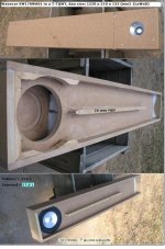
Maybe a small footprint T-TQWT could be of interest: See the pictures
My son has a very similar system (high SQ performance wise, size(and driver sizes)) in a small room (ca 10 m^2) using a single plate sub amp and a 7 channel main amp.
b
Attachments
Hi klankyman,
Maybe a small footprint T-TQWT could be of interest: See the pictures
My son has a very similar system (high SQ performance wise, size(and driver sizes)) in a small room (ca 10 m^2) using a single plate sub amp and a 7 channel main amp.
b
Thanks a lot for the suggestion. I've read about TQWT's, but I'm not sure I understand exactly what a T-TQWT is. From what I understand, the extra T stands for tapped, and implies that the drivers aren't on the outside of the enclosure, but rather in the dividing piece. Does that mean that the only place for accoustic output is the little slot? Or is there some other opening in the enclosure somewhere?
Hi ,
you can see some tapped horns in this tread. They are the flat boxes against the wall.
It's 48"X45" but only 11' deep. Please look for post # 26 and some others.
http://forums.audioholics.com/forums/showthread.php?t=49678&page=3
Danley Sound Labs THSPUD - Page 8 - Audioholics Home Theater Forums
you can see some tapped horns in this tread. They are the flat boxes against the wall.
It's 48"X45" but only 11' deep. Please look for post # 26 and some others.
http://forums.audioholics.com/forums/showthread.php?t=49678&page=3
Danley Sound Labs THSPUD - Page 8 - Audioholics Home Theater Forums
Last edited:
Thanks a lot for the suggestion. I've read about TQWT's, but I'm not sure I understand exactly what a T-TQWT is. From what I understand, the extra T stands for tapped, and implies that the drivers aren't on the outside of the enclosure, but rather in the dividing piece. Does that mean that the only place for accoustic output is the little slot? Or is there some other opening in the enclosure somewhere?
Hi Klankyman,
You’re right there is only one opening for the acoustic waves to escape.
Unlike an ordinary TQWT (Tapered-Quarter-Wave Tube) or a BR box having the acoustic summing at the far field areas a T-TQWT (Tapped-TQWT) acoustic summing takes place right where the port is located.
This is IMO an advantage when placed in crammed areas as the port can be very close to other surface areas without changing the apparent sound character.
I’ve tested aluminum drivers with Sd/port area exceeding a ¼ ratio, (though max 1/3 for quality paper cones) sounding IMO very well.
See the small T-TQWT IMO,high SQ sub I built last spring for a friend:
b
Attachments
Thanks a lot for your help, björno.
I have a few small questions. The design you simulated for me, is that a single driver in the enclosure like the last one you attached, or is it a double driver setup like your son's? If it's single driver I must say the output is quite impressive.
I'm a bit wobbly on the nomenclature for the different areas on hornresp. I think the following is the case, but please correct me if I'm wrong:
S1 is the biggest area, basically the size of the lid that covers up the big end of the tube.
S2 is the cross sectional area directly behind the woofer.
S3 is the cross sectional area directly in front of the woofer.
S4 is the size of the opening.
L12 is the distance from aforementioned S1 lid to the center of the driver.
L23 is the distance from the rear center of the driver, all the way along the tube, and around the fold, to the front center of the driver.
Is that all correct?
How exactly is L34 measured? if you just left the tube open at the smallest end, I'd assume it would be from the front center of the driver to the end of the tube. But if the smallest end is closed up, and the opening is instead directly in front of the driver like in your designs, from where to where do you measure?
S1 is the area at the closed end of the folded tube.
Usually in a tapped horn S1<<Sd and S2 and S3 and S4 >> S1
But these rules are not fixed. You can alter all the areas as you see fit and Hornresponse shows you what to expect from the changes.
L34 is the distance from the effective cone/piston centre to the centre of the S4.
It can be very small ~[driver diam / 2] or it can be much larger.
- Status
- This old topic is closed. If you want to reopen this topic, contact a moderator using the "Report Post" button.
- Home
- Loudspeakers
- Subwoofers
- Building a nice Subwoofer - questions.