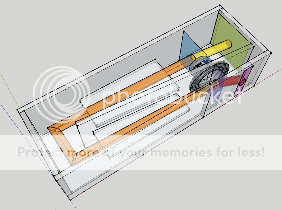
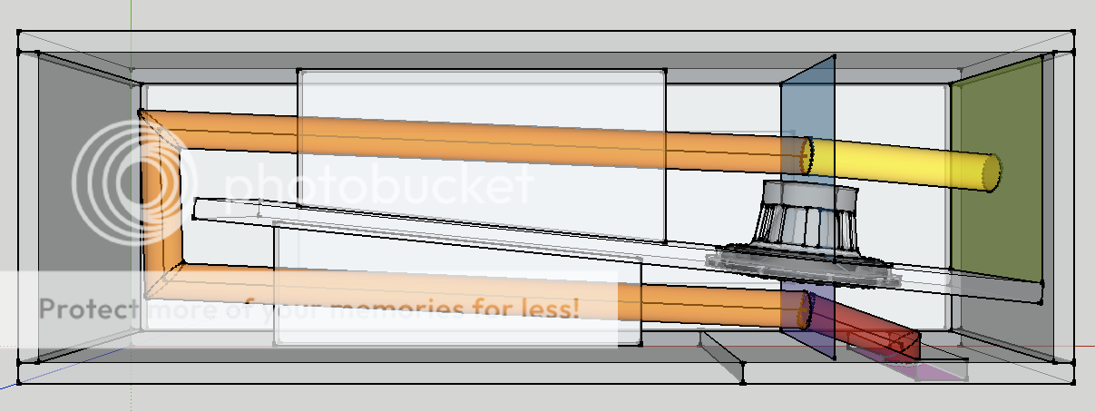
I made a real quick model in sketchup today. Would the following depict the correct way to build a T-TQWT?
The colored parts aren't depicting actual physical objects, but rather the areas/distances to be measured. Assuming the green area is S1, the blue area is S2, the purple area is S3 and the pink area is S4, the yellow length is L12, the orange length is L23 and the red distance is L34... is this the correct layout for such an enclosure?
The area between the divider and the left end of the enclosure needs to be exactly (S2+S3)/2 , right?
I'm definitely leaning towards building one or two of these, just to see how it works out, simply out of cheap 16 or 19mm MDF.
Meanwhile I'm still waiting on MCM, whose customer service, I must mention, has been very helpful so far.
An externally hosted image should be here but it was not working when we last tested it.
An externally hosted image should be here but it was not working when we last tested it.
The colored parts aren't depicting actual physical objects, but rather the areas/distances to be measured. Assuming the green area is S1, the blue area is S2, the purple area is S3 and the pink area is S4, the yellow length is L12, the orange length is L23 and the red distance is L34... is this the correct layout for such an enclosure?
The area between the divider and the left end of the enclosure needs to be exactly (S2+S3)/2 , right?
I'm definitely leaning towards building one or two of these, just to see how it works out, simply out of cheap 16 or 19mm MDF.
Meanwhile I'm still waiting on MCM, whose customer service, I must mention, has been very helpful so far.
I made a real quick model in sketchup today. Would the following depict the correct way to build a T-TQWT?
The colored parts aren't depicting actual physical objects, but rather the areas/distances to be measured. Assuming the green area is S1, the blue area is S2, the purple area is S3 and the pink area is S4, the yellow length is L12, the orange length is L23 and the red distance is L34... is this the correct layout for such an enclosure?
The area between the divider and the left end of the enclosure needs to be exactly (S2+S3)/2 , right?
I'm definitely leaning towards building one or two of these, just to see how it works out, simply out of cheap 16 or 19mm MDF.
Meanwhile I'm still waiting on MCM, whose customer service, I must mention, has been very helpful so far.
Hi Klankymen,
Your Sketchup drawings are really good
") and depict a T-TQWT in better ways than my oversimplified drawings I show here at diyAudio.
and depict a T-TQWT in better ways than my oversimplified drawings I show here at diyAudio.Your layouts are correct as far as I can see.
The only comment I have is: The top area of the box is = S2+S3)/2 + the area of the end of the divider, so for your case: The inner depth of the box should increase with 16 mm or 19 mm as you should compensate for the volume occupying by the divider.
b
Last edited:
Slow progress going on here, I realize, but I have a minor question I'd like to ask.
I want to put 4 binding posts on each subwoofer, so that I can externally switch between series and parallel connections, without having to open up the whole box. While researching prices, I found that I can obtain one such terminal plate:
for less money than the cost of a single pair of bindings posts:
of which I would of course require two pairs to offer the same amount of connections as with the plates.
However, as I am currently leaning towards a sealed box design (instead of vented, as originally thought), I am somewhat worried by how good the seal from such a flimsy plastic construction would be.
Do you think I can use one of those plastic plates without worrying about airleaks, or am I better of sticking with the pricier individual binding posts?
The price difference for the whole project would amount to about 25 euros, which is not an insignificant amount (that's more expensive than one driver is!).
I want to put 4 binding posts on each subwoofer, so that I can externally switch between series and parallel connections, without having to open up the whole box. While researching prices, I found that I can obtain one such terminal plate:
An externally hosted image should be here but it was not working when we last tested it.
for less money than the cost of a single pair of bindings posts:
An externally hosted image should be here but it was not working when we last tested it.
of which I would of course require two pairs to offer the same amount of connections as with the plates.
However, as I am currently leaning towards a sealed box design (instead of vented, as originally thought), I am somewhat worried by how good the seal from such a flimsy plastic construction would be.
Do you think I can use one of those plastic plates without worrying about airleaks, or am I better of sticking with the pricier individual binding posts?
The price difference for the whole project would amount to about 25 euros, which is not an insignificant amount (that's more expensive than one driver is!).
a 4pole Speakon would allow all the flexibility you need.
Each of the 4wires feeding the two drivers terminates in the socket.
You can drive them individually, or in parallel, or in series.
But then I'd have to resolder the Speakon connector every time I wish to change something (or recrimp my wires). But the whole point of what I'm trying to do here is to be able to change the circuit layout on the fly, without unscrewing or resoldering anything.
three cables.
One with two amplifier inputs, feeding the drivers separately.
One with the drivers in parallel, from a single amplifier.
One with drivers in series, from a single amplifier.
If one of those options is a non starter, then that leaves one spare cable, carefully labeled, in the van.
One with two amplifier inputs, feeding the drivers separately.
One with the drivers in parallel, from a single amplifier.
One with drivers in series, from a single amplifier.
If one of those options is a non starter, then that leaves one spare cable, carefully labeled, in the van.
OK, so I think I've finally come to a decision (I know, I'm really slow, I'm currently running these in some cheap mdf vented cabs), but I'm going to try to build some finished boxes.
I'm going to build three sealed boxes, linkwitz transformed via minidsp for a -3dB point at 40Hz, excursion limited for 101dB (98dB at 40Hz), however amp power limited at around 6dB less. These three will be used for Geddes style multisubs, above the room's lowest fundamental node.
I was originally going to use four of these, but instead I'm thinking of using my two remaining drivers to build a home-cinema style "infra"-sub, for use below 40Hz mainly, to give proper effects for movies. I'm thinking of a 20Hz tapped pipe, double folded.
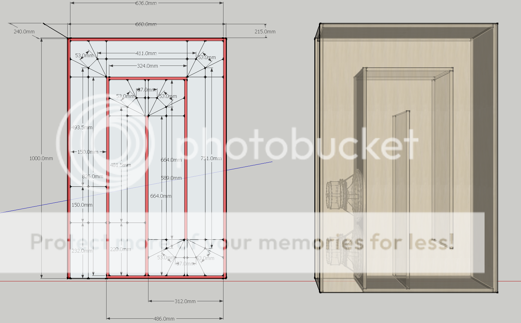
The thing is, whatever I build, it has to be no wider than 66cm external, and no higher than 24cm external. length is fairly flexible though.
Here's my ideas:
(12mm birch ply, to be braced with lots of 150mm x 40mm slats all along the horn path, doweled and glued)
Placement under my seat, thus functioning as both "buttkicker" and subwoofer. I like this plan because it only involves right angles, thus is easy enough for me to build. Any critiques? I've tried modeling it with expanding cross section, gets me more output, but less bottom end extension - so I'd rather go for the depth - 100dB in my small room with cabin gain below 40Hz should be nicely loud anyway - louder than my mains can keep up with.
I'm going to build three sealed boxes, linkwitz transformed via minidsp for a -3dB point at 40Hz, excursion limited for 101dB (98dB at 40Hz), however amp power limited at around 6dB less. These three will be used for Geddes style multisubs, above the room's lowest fundamental node.
I was originally going to use four of these, but instead I'm thinking of using my two remaining drivers to build a home-cinema style "infra"-sub, for use below 40Hz mainly, to give proper effects for movies. I'm thinking of a 20Hz tapped pipe, double folded.
The thing is, whatever I build, it has to be no wider than 66cm external, and no higher than 24cm external. length is fairly flexible though.
Here's my ideas:
(12mm birch ply, to be braced with lots of 150mm x 40mm slats all along the horn path, doweled and glued)
Placement under my seat, thus functioning as both "buttkicker" and subwoofer. I like this plan because it only involves right angles, thus is easy enough for me to build. Any critiques? I've tried modeling it with expanding cross section, gets me more output, but less bottom end extension - so I'd rather go for the depth - 100dB in my small room with cabin gain below 40Hz should be nicely loud anyway - louder than my mains can keep up with.
Hi jwmbro,
That looks nice (except for that nasty 75-110Hz hole), but have you taken a look at this thread:
http://www.diyaudio.com/forums/subwoofers/134369-dual-8-tapped-horn-th-spud.html
, it is one of the better reference threads if you want to build a dual driver tapped horn.
Regards,
That looks nice (except for that nasty 75-110Hz hole), but have you taken a look at this thread:
http://www.diyaudio.com/forums/subwoofers/134369-dual-8-tapped-horn-th-spud.html
, it is one of the better reference threads if you want to build a dual driver tapped horn.
Regards,
Hi jwmbro,
That looks nice (except for that nasty 75-110Hz hole), but have you taken a look at this thread:
http://www.diyaudio.com/forums/subwoofers/134369-dual-8-tapped-horn-th-spud.html
, it is one of the better reference threads if you want to build a dual driver tapped horn.
Regards,
Heya Oliver,
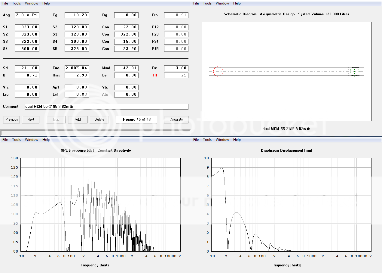
I have indeed read that thread some time ago, but never really tried the enclosures in it. So I modeled two or three of the enclosures in there, and for all cases got results like or similar to this:
xmax limited at 12Watt instead of 22Watt like my design, but similar spl and excursion.
Enclosure volume is around 250-260 liters net, so just over twice the size of my design (not to mention too wide for my 66cm space constraint).
Also, as for the hole above 70Hz, I realize that that's not ideal, but I'm struggling to make anything else within my size constraints (ie preferably <150l) that does better there and still reaches down to 20Hz. In fact, I'd even like to go even lower, but my DSP only supports highpasses down to 20Hz, so any output below that would be wasted).
Also, bear in mind I have 3 closed subs covering nicely above 40Hz (each one equivalent to the purple curve, add a few dB for summation):

Also, I approximated the passband of my tapped "horn" in winisd, to get some comparison figures, and also apply some filters to it (no signal processing in hornresp).
The hornresp results are shown in yellow.
Orange shows how I'd like to use it, with 2nd order bandpass between 20Hz and 50Hz (with the rising response, the 50Hz lowpass tames the peak, and extends the usage window up to about 70Hz, so that's about 1 and 3/4 octaves).
At this output, it's excursion safe within passband, and pretty close below (the only overexcursion is a 5mm peak at 16Hz - compared to the 4.1mm xmax), but I believe the times at which I'm going to play a 16Hz sinewave at full blast will be very seldom. (and even if - a rare case of slightly exceeding xmax shouldn't do much harm - I unfortunately can't find a quoted xmech figure).
A plus-point for my design, is that it can be built using a single sheet (=3 m^2) of 12mm ply, which already costs 60€ over here.
So, by all means, this design looks pretty promising to me, if there's any reason I should abort this plan, please let me know.
Worst case I'd be out around 60€, which wouldn't be too tragic.
Hi jwmbro,
I just wanted to make sure that you are aware of that style of enclosure/construction, having one of the drivers mounted inverted will help in distortion cancellation. Obviously, the size would be determined by the drivers you use, tapped horns are very driver specific.
Regards,
I just wanted to make sure that you are aware of that style of enclosure/construction, having one of the drivers mounted inverted will help in distortion cancellation. Obviously, the size would be determined by the drivers you use, tapped horns are very driver specific.
Regards,
Thanks for the tips. I've played around, both from your baseline, and from some proposed in the TH-SPUD thread, and while I've had some better results, I haven't had anything I've been able to fold into my size constraints.
Here's the best one I've been able to do, using the full dimensions of my size restriction (200cm x 66cm x 24cm external). Height is, as usual, 21.5mm internal.
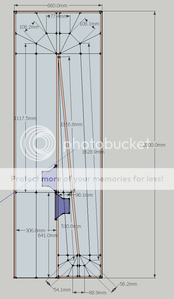
It just barely extends to 20Hz, I was hoping to get one or two Hz below that, for margin of error, but that's all the bottom end extension I can manage from a two-fold 2m long design.
It does get me a good 4dB more output while forfeiting those bottom 2 Hz, also it gives a smoother response (and no huge dip right outside the passband), although I do have plenty of DSP available for this sub.
However, it's exacly twice the external volume (2m long instead of 1m long), and it needs almost twice as much wood. (approx 1+2/3 sheets instead of 1 sheet - 5m^2 instead of 3m^2) Also it will be a lot more impractical to transport, at 2m length instead of 1m length.
So at this point I'm debating if those 4dB extra output are worth the downsides of higher cost, size, and F3.
What do you think? I've HornRespWizarded some a lot nicer designs in less than 200l, but nothing I've been able to fold to fit the space it needs to.
Here's the best one I've been able to do, using the full dimensions of my size restriction (200cm x 66cm x 24cm external). Height is, as usual, 21.5mm internal.
It just barely extends to 20Hz, I was hoping to get one or two Hz below that, for margin of error, but that's all the bottom end extension I can manage from a two-fold 2m long design.
It does get me a good 4dB more output while forfeiting those bottom 2 Hz, also it gives a smoother response (and no huge dip right outside the passband), although I do have plenty of DSP available for this sub.
However, it's exacly twice the external volume (2m long instead of 1m long), and it needs almost twice as much wood. (approx 1+2/3 sheets instead of 1 sheet - 5m^2 instead of 3m^2) Also it will be a lot more impractical to transport, at 2m length instead of 1m length.
So at this point I'm debating if those 4dB extra output are worth the downsides of higher cost, size, and F3.
What do you think? I've HornRespWizarded some a lot nicer designs in less than 200l, but nothing I've been able to fold to fit the space it needs to.
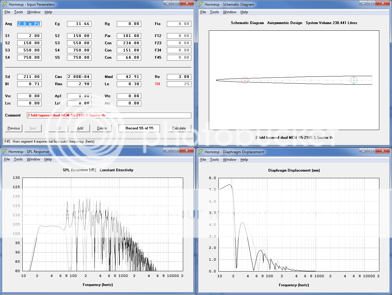
you have a 5.5m TH.
That will reproduce low bass.
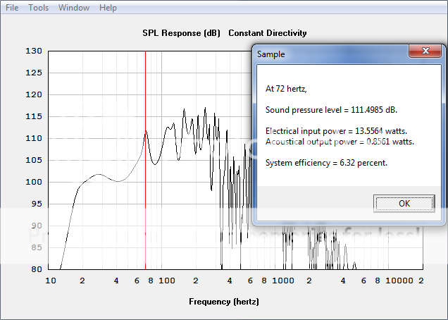
104dB from 17W of input seems very low, ~92dB/W
4mm & 7mm displacement @ 17W ! What are your Xmax & available power?
What about a single driver smaller box? and if it works, but you need more SPL, then build a copy or improve it to where your ears tell you to go.
BTW,
I've tried, but I can't design a TH that simulates well. I can't offer guidance that could help.
That will reproduce low bass.
104dB from 17W of input seems very low, ~92dB/W
4mm & 7mm displacement @ 17W ! What are your Xmax & available power?
What about a single driver smaller box? and if it works, but you need more SPL, then build a copy or improve it to where your ears tell you to go.
BTW,
I've tried, but I can't design a TH that simulates well. I can't offer guidance that could help.
Last edited:
hi jwmbro,
Another nice drawing, what program do you use? Horns (even tapped ones) tend to be big, don't they. That seems to be one reason bjorno likes the T-TQWT enclosure.
Just for an excercise: change S1 to 149 and L12 to 0.10. That's what you would have with a throat chamber coupling to the end very end of the horn. (To be correct you'd also have to add a throat chamber: Ap1/Lpt/Vtc/Atc.)
I'll try to look at this tonight.
Regards,
- Status
- This old topic is closed. If you want to reopen this topic, contact a moderator using the "Report Post" button.
- Home
- Loudspeakers
- Subwoofers
- Building a nice Subwoofer - questions.