Hi Oliver,
I use Google SketchUp (it's free!), a fairly basic cad program which I've been using for some years now.
There are probably easier ways to work on folding, but after doing some basic folding in my head, I really have to sketch it out to get the correct dimensions to compare with hornresp.
I'm not really able to transmit every hornresp input into a proper design, but perhaps some designs simply aren't foldable. And those that are, don't necessarily conform to my size restrictions.
Tell me about it! It's so easy to get them huge, which is why I'm all the more impressed by things such as jbell's ~200l design getting such crazy output.
On a related matter - I'm often confused as to what really constitutes a horn, and what a pipe, and what a tube.
I think I get most the stuff:
QW means the path length is a quarter wavelength of the driver's Fs.
Tapped means that the front output and the rear output are both used, combined using a fairly long phase shifting path.
Tapered means that the tube gets thicker as it goes along.
But when is a horn a horn, and when is it just a tapered tube? I'm confused. Does it even matter? They all simulate as TH in hornresp anyway, right?
Interesting... throat chamber is the same as compression chamber I take it? I see how it changes my result, though not necessarily for the better.
Slightly unrelated: It seems to me that many physical shapes can be modeled in quit different ways using hornresp, getting the same resulting schematic and output.
Thanks!
hi jwmbro,
Another nice drawing, what program do you use?
I use Google SketchUp (it's free!), a fairly basic cad program which I've been using for some years now.
There are probably easier ways to work on folding, but after doing some basic folding in my head, I really have to sketch it out to get the correct dimensions to compare with hornresp.
I'm not really able to transmit every hornresp input into a proper design, but perhaps some designs simply aren't foldable. And those that are, don't necessarily conform to my size restrictions.
Horns (even tapped ones) tend to be big, don't they. That seems to be one reason bjorno likes the T-TQWT enclosure.
Tell me about it! It's so easy to get them huge, which is why I'm all the more impressed by things such as jbell's ~200l design getting such crazy output.
On a related matter - I'm often confused as to what really constitutes a horn, and what a pipe, and what a tube.
I think I get most the stuff:
QW means the path length is a quarter wavelength of the driver's Fs.
Tapped means that the front output and the rear output are both used, combined using a fairly long phase shifting path.
Tapered means that the tube gets thicker as it goes along.
But when is a horn a horn, and when is it just a tapered tube? I'm confused. Does it even matter? They all simulate as TH in hornresp anyway, right?
Just for an excercise: change S1 to 149 and L12 to 0.10. That's what you would have with a throat chamber coupling to the end very end of the horn. (To be correct you'd also have to add a throat chamber: Ap1/Lpt/Vtc/Atc.)
I'll try to look at this tonight.
Interesting... throat chamber is the same as compression chamber I take it? I see how it changes my result, though not necessarily for the better.
Slightly unrelated: It seems to me that many physical shapes can be modeled in quit different ways using hornresp, getting the same resulting schematic and output.
Thanks!
Simply...
A Horn is flared, and gets larger as you move towards the throat.
A Pipe are Tube is really the same thing, and has a constant cross-sectional area. Normally, a cylinder is called a Pipe, and a square/rectangle resonator is a Tube.
A QW(R-T-P) is a quarter wave (resonator-tube-pipe). The "quarter" part comes from the path length of the enclosure being the QW length of the enclosures low frequency cutoff. The cutoff is the point at which the enclosure begins to stop loading the driver.
A Tapered design can be one of many different things. It refers to a Pipe/Tube in which the area is not constant from the throat to the mouth. The small end varies from alignment to alignment, to make things fun.")
A Horn is flared, and gets larger as you move towards the throat.
A Pipe are Tube is really the same thing, and has a constant cross-sectional area. Normally, a cylinder is called a Pipe, and a square/rectangle resonator is a Tube.
A QW(R-T-P) is a quarter wave (resonator-tube-pipe). The "quarter" part comes from the path length of the enclosure being the QW length of the enclosures low frequency cutoff. The cutoff is the point at which the enclosure begins to stop loading the driver.
A Tapered design can be one of many different things. It refers to a Pipe/Tube in which the area is not constant from the throat to the mouth. The small end varies from alignment to alignment, to make things fun.
Hi James,
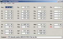
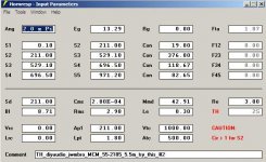
I'm using an older version of ACAD(14). Without a drafting program the more complex forms of tapped horns would be difficult to make.
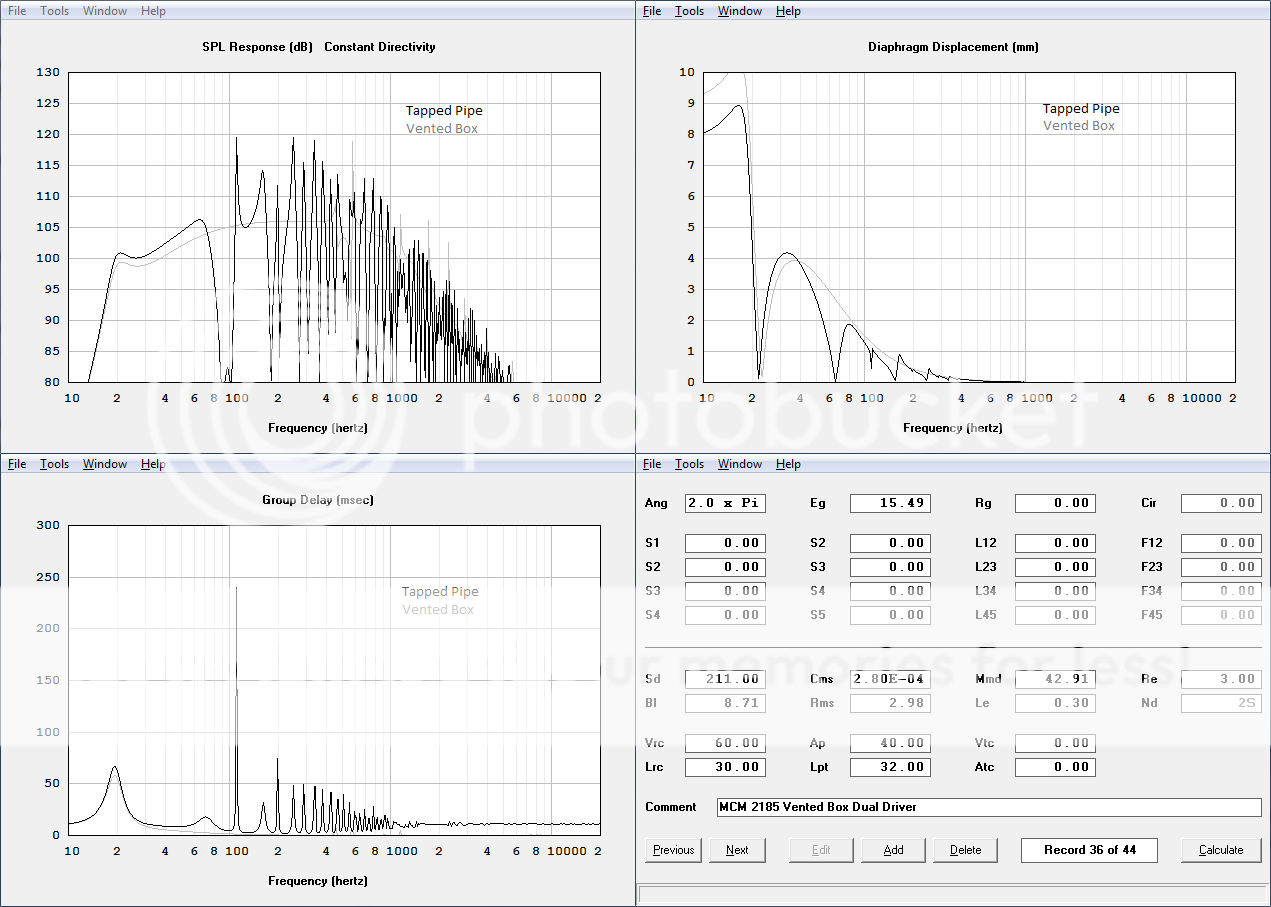
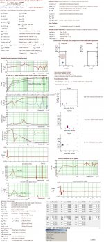
I'll attach a concept Hornresp input screen, and a sketch (concept only, not a drawing) using your maximum dimensions. This shows one way to implement a throat coupling chamber (compression chamber). The horn path turns out longer than I would make it for that particular driver, but it gets you below 20Hz. It's less raggedy than some of the long horn home theater tapped horns, the slightly drooping response (at the low end) is desirable to compensate for room gain. I'd almost bet that the high end would be much less than indicated in Hornresp. When you play around with this in Hornresp you'll find that increasing S5 will raise the mid/upper bass more than the very bottom.
On the subject of Hornresp, I find it amazing too how many different enclosures we can model with the relatively small set of variables. By the way, have you measured the Thiel/Small parameters for these drivers? My experience with MCM drivers has not been too good as to the accuracy of their data (and that sentence was edited by the legal department).
Ultimately, there is really only one way to find if this works, and that's to build it. I recommend to use the least expensive material you can get your hands on, people get all bent out of shape about this subject, but I can't see why for initial experiments, e.g.: 1/2" particle board or OSB.
I'm sorry that I don't have the time to run through the complete folding with any accuracy, but you're doing fine by yourself as far as I can see.
Just more stuff to think about.
Regards,
I'm using an older version of ACAD(14). Without a drafting program the more complex forms of tapped horns would be difficult to make.
I'll attach a concept Hornresp input screen, and a sketch (concept only, not a drawing) using your maximum dimensions. This shows one way to implement a throat coupling chamber (compression chamber). The horn path turns out longer than I would make it for that particular driver, but it gets you below 20Hz. It's less raggedy than some of the long horn home theater tapped horns, the slightly drooping response (at the low end) is desirable to compensate for room gain. I'd almost bet that the high end would be much less than indicated in Hornresp. When you play around with this in Hornresp you'll find that increasing S5 will raise the mid/upper bass more than the very bottom.
On the subject of Hornresp, I find it amazing too how many different enclosures we can model with the relatively small set of variables. By the way, have you measured the Thiel/Small parameters for these drivers? My experience with MCM drivers has not been too good as to the accuracy of their data (and that sentence was edited by the legal department
).Ultimately, there is really only one way to find if this works, and that's to build it. I recommend to use the least expensive material you can get your hands on, people get all bent out of shape about this subject, but I can't see why for initial experiments, e.g.: 1/2" particle board or OSB.
I'm sorry that I don't have the time to run through the complete folding with any accuracy, but you're doing fine by yourself as far as I can see.
Just more stuff to think about.
Regards,
Attachments
That should be larger as you move towards the mouth.Simply...
A Horn is flared, and gets larger as you move towards the throat.
I hate the editing limitations here.
Here's my ideas:
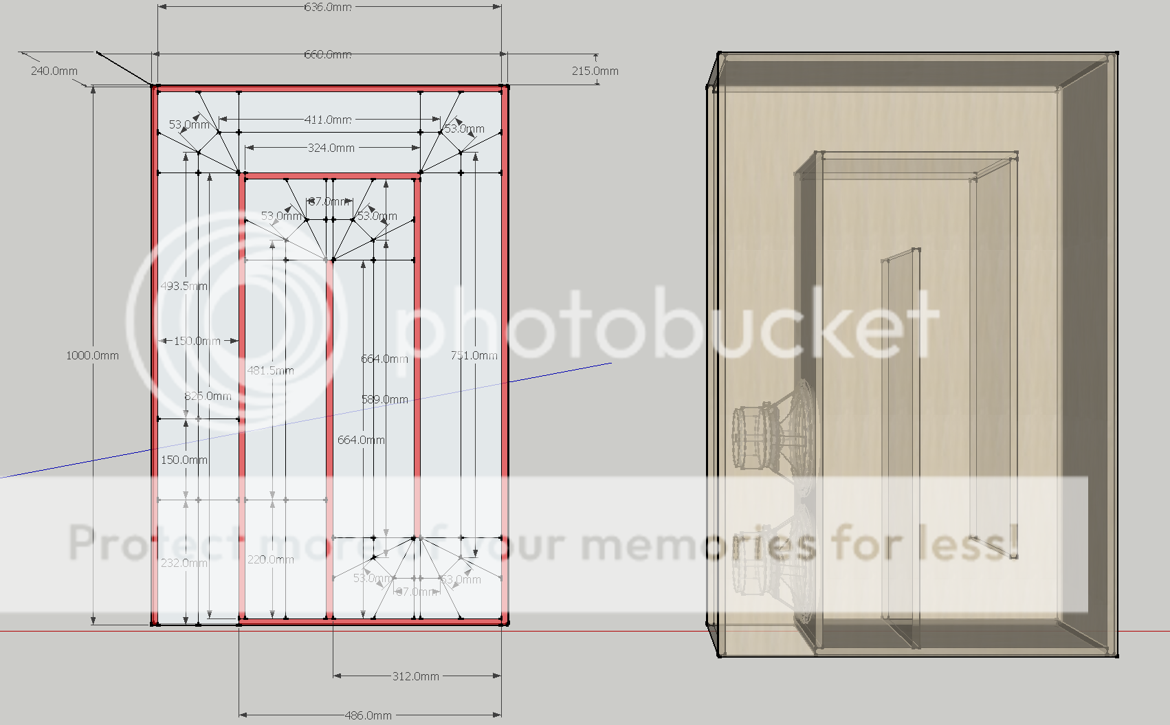
(12mm birch ply, to be braced with lots of 150mm x 40mm slats all along the horn path, doweled and glued)
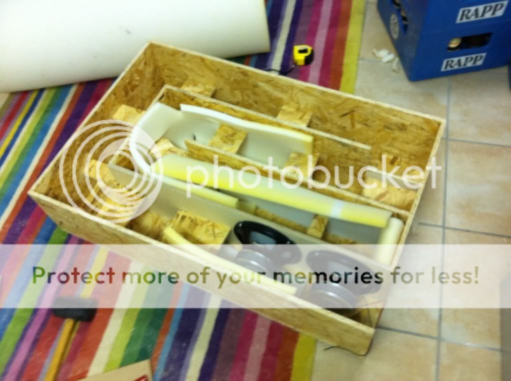
Hi. For building a tapped tube sub such as above, would this kind of foam be any good for lining/stuffing?

Edit: It's RG 25/40, if that means anything to anybody
Hi James,
The open pore foam in your picture looks fine. Take a look at geitmans thread as to the impact of damping material:
http://www.diyaudio.com/forums/subwoofers/134369-dual-8-tapped-horn-th-spud.html
As to the folding in your drawing, I would recommend a tapered horn as in:
http://www.diyaudio.com/forums/subwoofers/143714-lab12-tapped-horn.html
Happy New Year,
Regards,
Hi James,
The open pore foam in your picture looks fine. Take a look at geitmans thread as to the impact of damping material:
http://www.diyaudio.com/forums/subwoofers/134369-dual-8-tapped-horn-th-spud.html
As to the folding in your drawing, I would recommend a tapered horn as in:
http://www.diyaudio.com/forums/subwoofers/143714-lab12-tapped-horn.html
Happy New Year,
Regards,
Happy New Year as well!
Well, I got the wood for the tapped tube (no taper) before reading your post. But I also went ahead and got the foam, a 2 sq m sheet should allow me to do some experimentation. Just building a prototype now anyways, to get an idea of horns.
In any case:
one 3m^2 (4x8ft) sheet of 12mm (1/2") MDF: 33€
one 3m^2 (4x8ft) sheet of 12mm (1/2") OSB: 39€
one 3m^2 (4x8ft) sheet of 12mm (1/2") Birch Ply: 60€
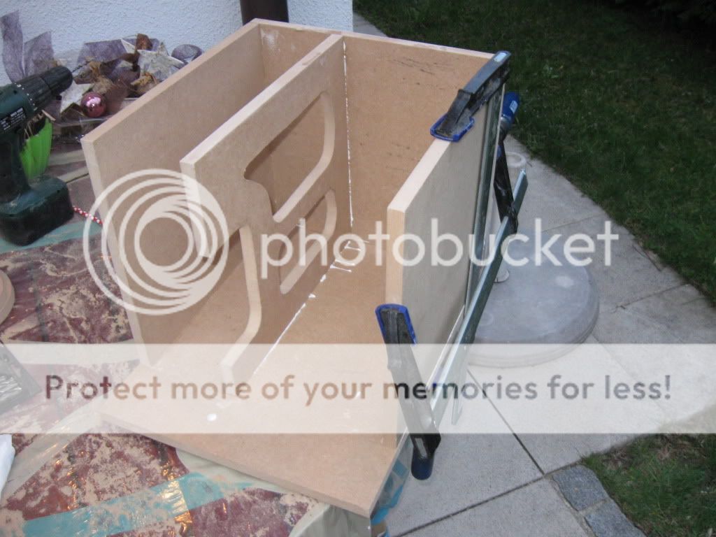
Note to self: Don't!!! cheap out and buy OSB, the 20€ savings for a 1-sheet test design aren't worth it:
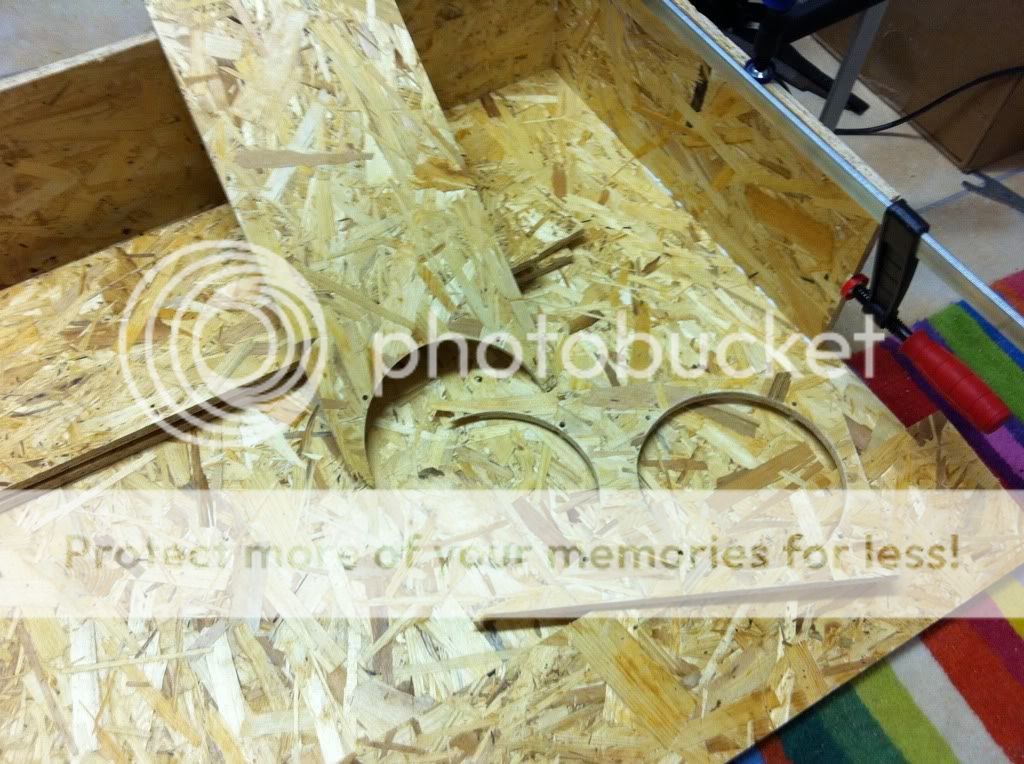 Off to buy some more plywood tomorrow.
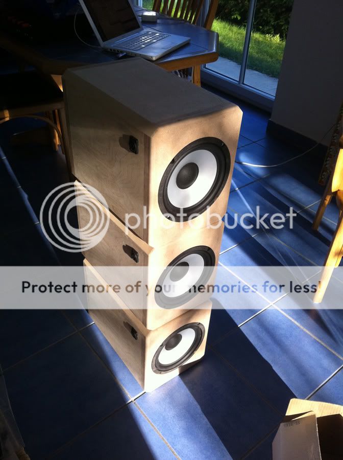
Well, despite having read that you shouldn't build tapped horns with all parallel walls, I went ahead and built this:
(I have since flipped one of the drivers around, that was just a first testing)
Reasons why I went ahead and built it anyway:
a) It was my own design, and though not as good as other people's, it's a nice learning experience to design something from the ground up and see how it sounds.
b) My woodworking (and workshop equipment) is not very good (though I'm improving the more practice (and tools) I get), so angled cuts are a bit of a problem.
c) wanted to try making something from OSB. Lesson learned: OSB is crap. Stick to plywood, or if you have to make a cheaper (but heavy) protoype, use MDF.
In any case, as for my impressions: Wow, this is nice deep solid bass.
On the other hand, compared to some cheapy MDF vented boxes I built, bass isn't that much more impressive.
I've done some simulations, and I'm rather surprised at how close at 20Hz a dual driver vented box is to the horn (all the while being half the volume)
It gives up about 2dB at 20Hz (both designs xmax limited, and both requiring a 20Hz highpass), and is surprisingly lower in group delay (one of the reasons I had originally discarded vented boxes was the high group delay). And, the response of the vented box is flat for 4 octaves, which is more than any TH I've ever seen can achieve.
Oh, and by the way, even with the small (3" diameter) reflex pipe, my calculations reveal max vent speed of 15 m/s at 20Hz (would be 20 m/s without the highpass), which should mean no chuffing at all.
I realize I'm rambling a bit here, but one really does learn the most simply by trying and doing things.
Right now I'm working on building a 4-channel amplifier for this, but I have the wood for some dual closed boxes already sawed up at home, just needs to be routed and glued.
The design is going to be very similar to this planet10 concept:
Building speakers is freaking addictive, and I'm working on way too many projects at once, including the ones still in the design stage.
(I have since flipped one of the drivers around, that was just a first testing)
Reasons why I went ahead and built it anyway:
a) It was my own design, and though not as good as other people's, it's a nice learning experience to design something from the ground up and see how it sounds.
b) My woodworking (and workshop equipment) is not very good (though I'm improving the more practice (and tools) I get), so angled cuts are a bit of a problem.
c) wanted to try making something from OSB. Lesson learned: OSB is crap. Stick to plywood, or if you have to make a cheaper (but heavy) protoype, use MDF.
In any case, as for my impressions: Wow, this is nice deep solid bass.
On the other hand, compared to some cheapy MDF vented boxes I built, bass isn't that much more impressive.
I've done some simulations, and I'm rather surprised at how close at 20Hz a dual driver vented box is to the horn (all the while being half the volume)
It gives up about 2dB at 20Hz (both designs xmax limited, and both requiring a 20Hz highpass), and is surprisingly lower in group delay (one of the reasons I had originally discarded vented boxes was the high group delay). And, the response of the vented box is flat for 4 octaves, which is more than any TH I've ever seen can achieve.
Oh, and by the way, even with the small (3" diameter) reflex pipe, my calculations reveal max vent speed of 15 m/s at 20Hz (would be 20 m/s without the highpass), which should mean no chuffing at all.
I realize I'm rambling a bit here, but one really does learn the most simply by trying and doing things.
Right now I'm working on building a 4-channel amplifier for this, but I have the wood for some dual closed boxes already sawed up at home, just needs to be routed and glued.
The design is going to be very similar to this planet10 concept:
An externally hosted image should be here but it was not working when we last tested it.
Building speakers is freaking addictive, and I'm working on way too many projects at once, including the ones still in the design stage.
Last edited:
..On the other hand, compared to some ..., bass isn't that much more impressive...
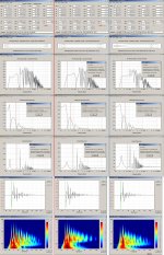
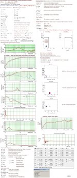
No doubt, I simulated your 'tapped pipe' design: See the complying results in the first column/ picture:
..I've done some simulations, and I'm rather surprised at how close at 20Hz a dual driver vented box is to the horn (all the while being half the volume)..
If two bad designs are compared, one will always be a winner. It gives up about 2dB at 20Hz (both designs xmax limited, and both requiring a 20Hz highpass), and is surprisingly lower in group delay (one of the reasons I had originally discarded vented boxes was the high group delay)...
What BW are you targeting?Looks you have targeted ~60 Hz for an upper boundary.
..And, the response of the vented box is flat for 4 octaves, which is more than any TH I've ever seen can achieve...
No way, See the submitted MJK simulations where only the heavily stuffed box and port design would be considered to incorporate a flat response up to ~50 Hz where f-3dB is in the vicinity too.
...Oh, and by the way, even with the small (3" diameter) reflex pipe, my calculations reveal max vent speed of 15 m/s at 20Hz (would be 20 m/s without the highpass), which should mean no chuffing at all.
I disagree again, See the simulations showing if exceeding 7W (if the box is stuffed): the port air velocity would be more than 30 m/S.
b
Attachments
Morning bjorno!
Wow, long reply, thanks very much for all the feedback. I'll try to reply to each of points you address individually.
I'm a bit curious how come you used a different Cms (thus also different Vas) figure than me.... due to this difference your simulation comes out even peakier than mine. EDIT: Never mind, I think I've figured this one out, you're using a higher Fs.
Perhaps we may both be wrong - I really should make my next investment a woofer-tester so I can measure the params.
No doubt, I'm only a beginner at this, and while there are surely better designs to be made, so far this is the best I can come up with at this stage. But as long as I learn from my actions and mistakes, I'm happy.
Ideally I would like to have a flat 20Hz-80Hz range of 100dB SPL.
If I had to make sacrifices, I'd rather lose the top octave than the bottom octave. So I'd prefer 20Hz-40Hz if that was all I can get, rather than give up bottom end extension.
Perhaps I should mention, I have DSP at my disposal for this project, and also it will mainly be used for movies. For relaxed music listening this often won't even be in use. So SPL and depth are a higher priority than musicality.
To be quite honest, the main thing I was looking for when making my design was not the flatness of the curve, but rather this:
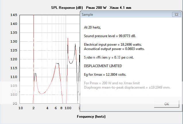
Max SPL is >100dB all the way from 20Hz to 80Hz.... DSP can handle the rest.
Wow, interesting how extremely 3 simulations of the same thing in 3 different programs can differ. Sometimes WinISD and HornResp show the exact same thing, and sometimes they differ wildly by >10dB. It's interesting.
Also, your post has finally prompted me to spend my first ever cash on audio software (I'm a very reluctant person to ever spend cash on any type of software). I just sent €19.20 in the way of Martin J King's paypal account! Looking forward to learning to use the spreadsheets.

So, getting back to the very first reply in this thread:
Well, some two years after receiving this advice, here's me following it:
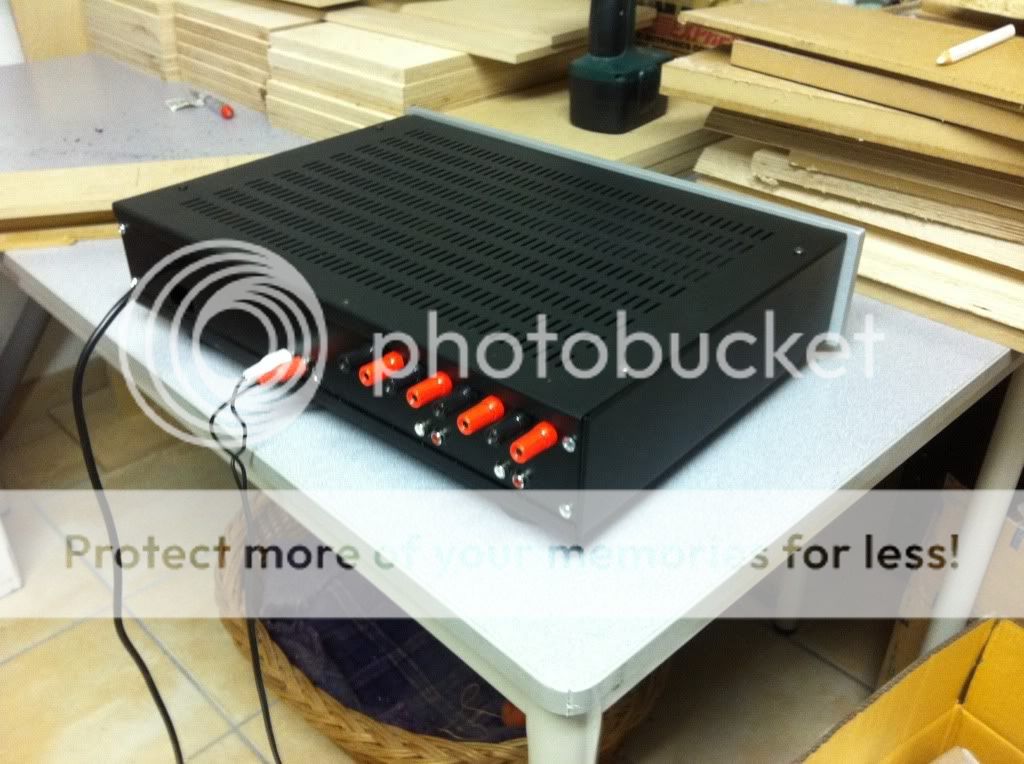
standalone 4-channel class-d subwoofer amp with integrated DSP. 'Tis currently a work in progress, will share some more pictures when I'm finished. This is what will power all my subwooferage:
Wow, long reply, thanks very much for all the feedback. I'll try to reply to each of points you address individually.
No doubt, I simulated your 'tapped pipe' design: See the complying results in the first column/ picture:
I'm a bit curious how come you used a different Cms (thus also different Vas) figure than me.... due to this difference your simulation comes out even peakier than mine. EDIT: Never mind, I think I've figured this one out, you're using a higher Fs.
Perhaps we may both be wrong - I really should make my next investment a woofer-tester so I can measure the params.
No doubt, I'm only a beginner at this, and while there are surely better designs to be made, so far this is the best I can come up with at this stage. But as long as I learn from my actions and mistakes, I'm happy.
What BW are you targeting?Looks you have targeted ~60 Hz for an upper boundary.
Ideally I would like to have a flat 20Hz-80Hz range of 100dB SPL.
If I had to make sacrifices, I'd rather lose the top octave than the bottom octave. So I'd prefer 20Hz-40Hz if that was all I can get, rather than give up bottom end extension.
Perhaps I should mention, I have DSP at my disposal for this project, and also it will mainly be used for movies. For relaxed music listening this often won't even be in use. So SPL and depth are a higher priority than musicality.
To be quite honest, the main thing I was looking for when making my design was not the flatness of the curve, but rather this:
Max SPL is >100dB all the way from 20Hz to 80Hz.... DSP can handle the rest.
No way, See the submitted MJK simulations where only the heavily stuffed box and port design would be considered to incorporate a flat response up to ~50 Hz where f-3dB is in the vicinity too.
I disagree again, See the simulations showing if exceeding 7W (if the box is stuffed): the port air velocity would be more than 30 m/S.
b
Wow, interesting how extremely 3 simulations of the same thing in 3 different programs can differ. Sometimes WinISD and HornResp show the exact same thing, and sometimes they differ wildly by >10dB. It's interesting.
Also, your post has finally prompted me to spend my first ever cash on audio software (I'm a very reluctant person to ever spend cash on any type of software). I just sent €19.20 in the way of Martin J King's paypal account! Looking forward to learning to use the spreadsheets.
So, getting back to the very first reply in this thread:
One advantage with a "stand alone" is that its practical to use just one amp with two subs, but its also good value with very nice funtions, and made in Germany
Well, some two years after receiving this advice, here's me following it:
standalone 4-channel class-d subwoofer amp with integrated DSP. 'Tis currently a work in progress, will share some more pictures when I'm finished. This is what will power all my subwooferage:
So, long time no reports here. After some time I spent occupied with other things, I finished up the bulk of the work of this project.
Many thanks go out, in no particular order, to:
- Duke LeJeune of AudioKinesis for his advice on multisub setups and small vented boxes
- Earl Geddes for his Multisub approach detailed in this thread
- Markus Mehlau, despite his occasional bickering, who has contributed much useful information on multisub setups, particularly this very helpful summary
- Dave Dlugos for all his designs, particularly this push-push concept with its reduced cabinet vibrations
- and of course everybody who has contributed to this thread
Building the subs
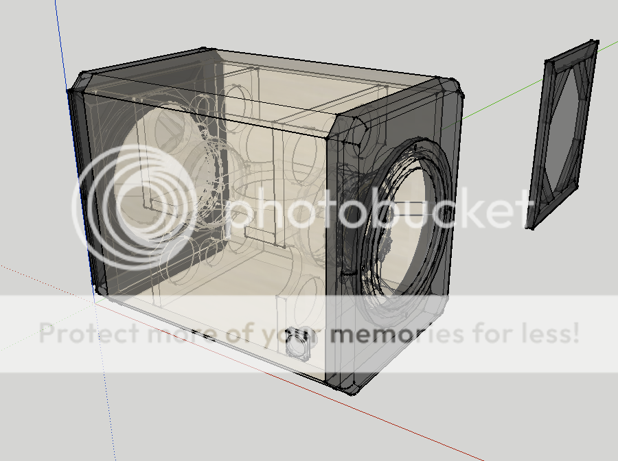
Before building, I made a model in Sketchup:
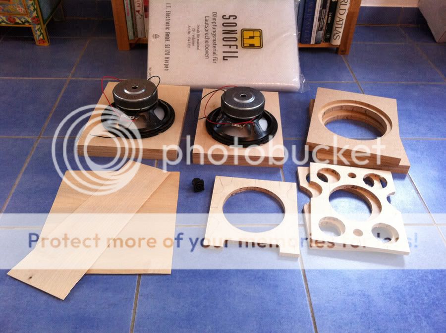
Here are the Basic ingredients:
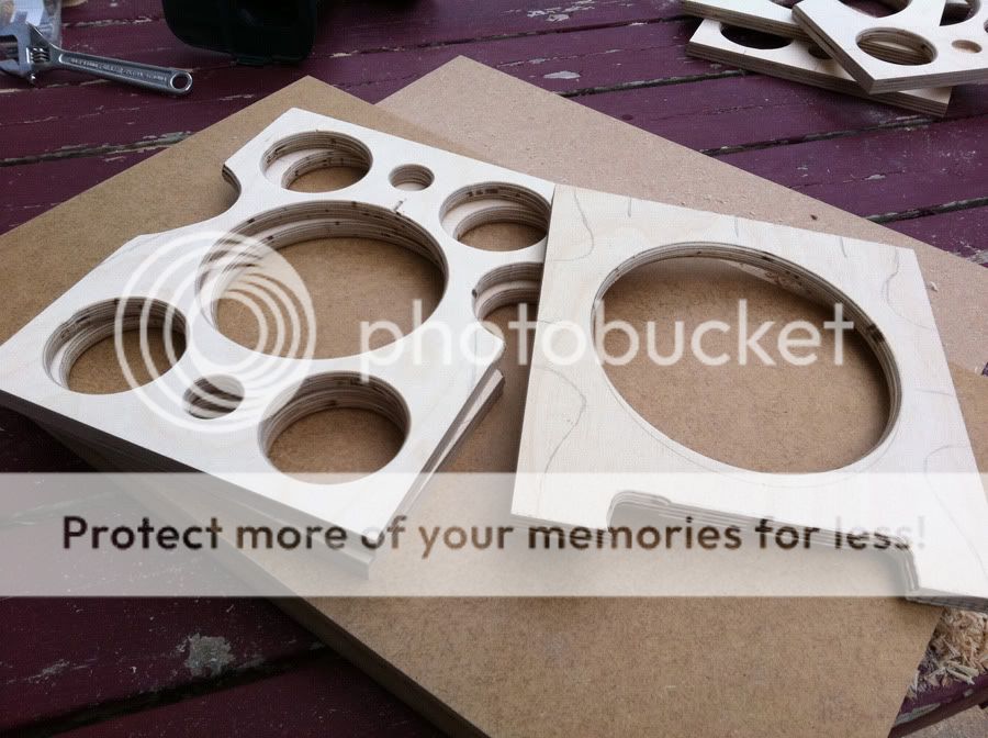
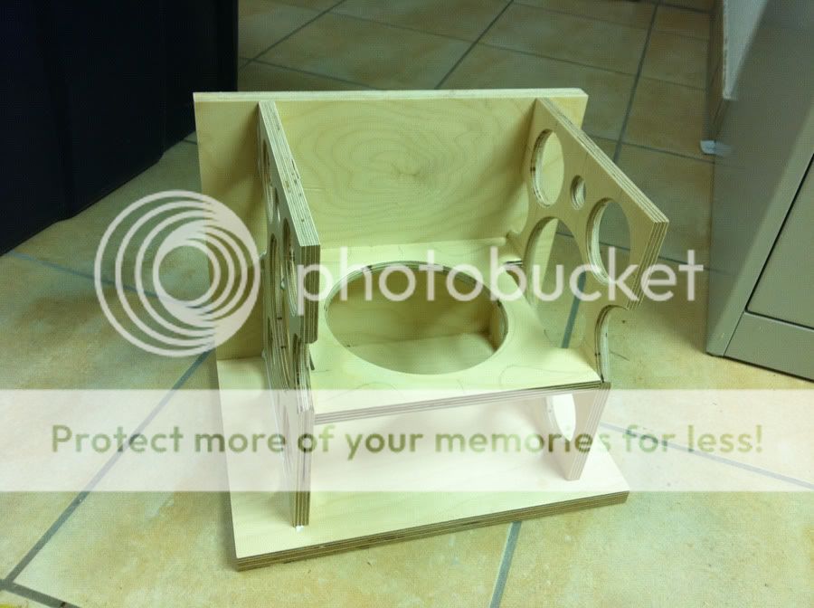
The braces, which are made of 12mm (1/2") birch ply, after getting the air holes routed in, get a quick roundover routed, because I'm too lazy to sand down all the edges:
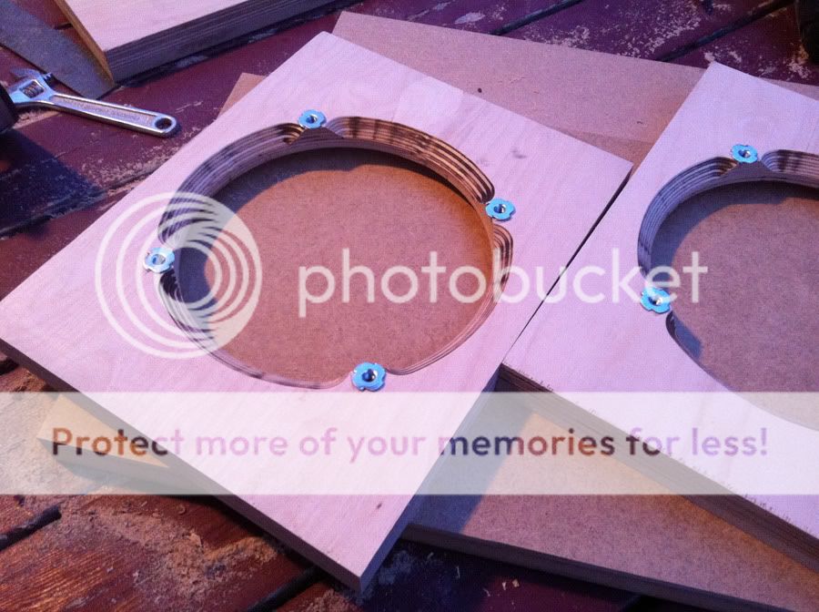
The baffles consist of 18mm (3/4") birch ply as a structural component, with 10mm (3/8") MDF glued on, which serves the purpose of recessing the woofers without losing stability by routing away plywood. Due to the thickness of the wood, it is chamfered around the back, to allow airflow, and T-nuts are put in.
The body of the sub is also made of 18mm (3/4") birch ply. The braces are glued slighly asymetrically, as not to create equal resonances.
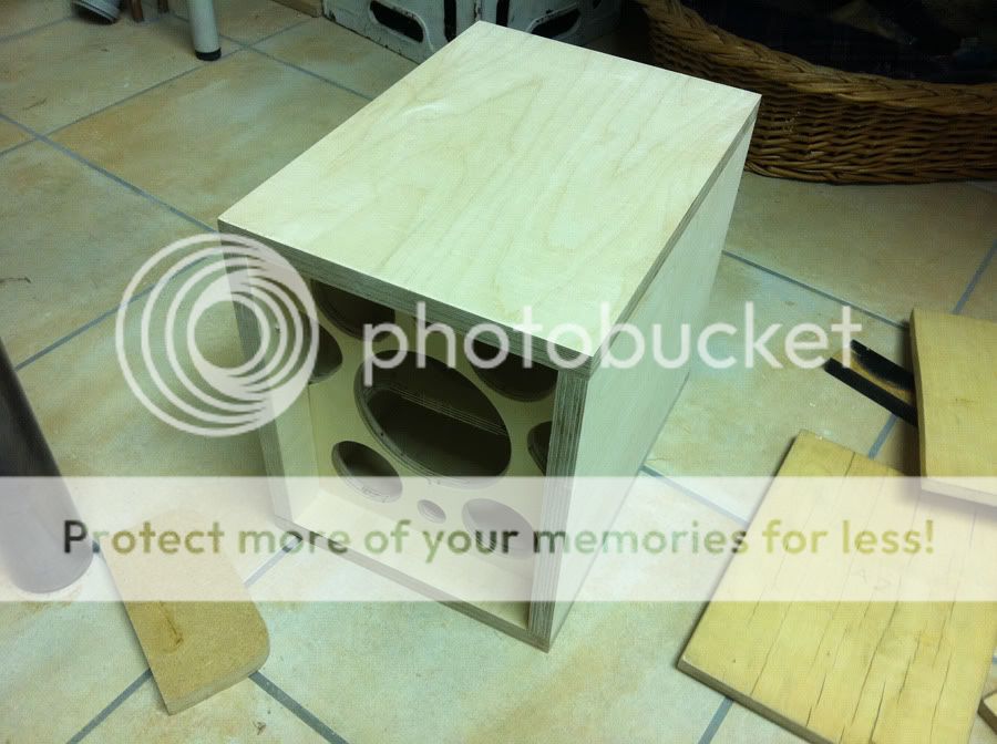
The rest of the body gets glued up, and the edges of the top and bottom (which are slightly wider then they need to be) are trimmed with my absolute favorite woodworking tool - the flush router bit.
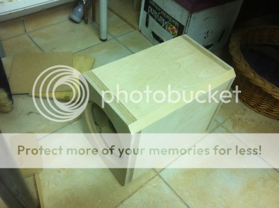
Then the baffles are glued on, once again trimmed down with my favorite flush router bit, and the edges of the sub are chamfered.
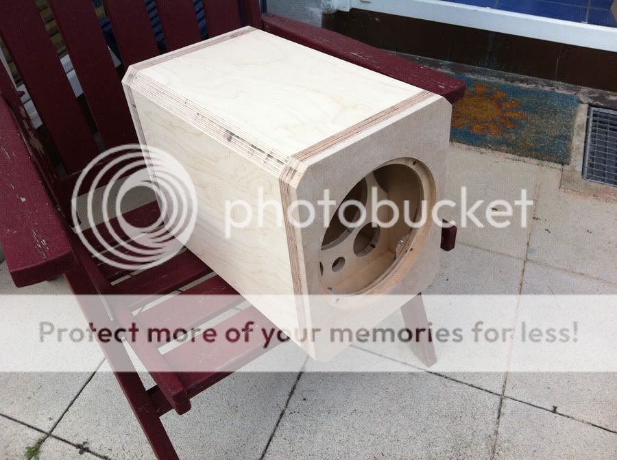
After chamfering the edges, some leftover bits of birch veneer I had from my last project were applied to cover up the open edges of the plywood. Also the baffle edges are rounded over. Not that it would be acoustically necessary with with the large wavelengths involved, but the idea is to match the appearance of my speakers.
After this, I drilled holes for and inserted the Speakon plug.

Multiply the process times 3, and you get the following stack:
And here's a picture of one of the subwoofers setup under my computer desk.
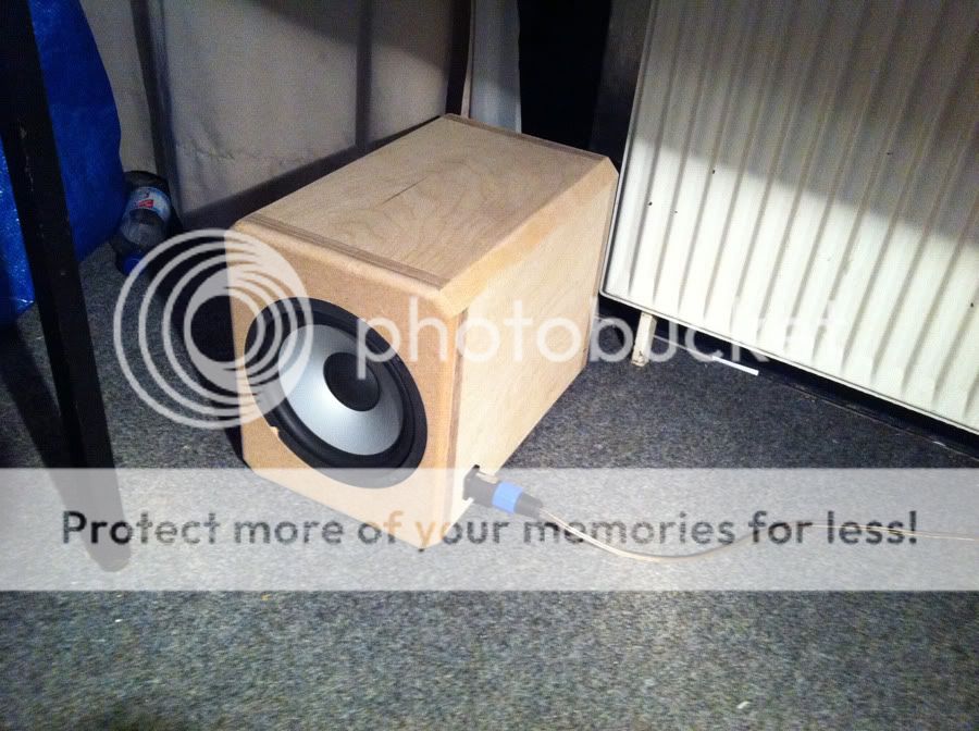
The sub isn't completely finished, but it's unfortunately already too cold to properly spraypaint outside, so painting the baffles black will need to wait until the springtime.
Each sub has a volume of approximately 15 liters, perhaps more considering the stuffing (Sonofil), but as you can see from this sketchup result, the enclosures are too small to produce proper bass naturally:
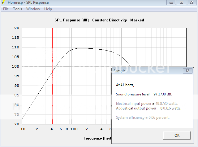
However my amplifier has a a built-in DSP, and I use Linkwitz transform to flatten the subs out to a -3dB point of about 40Hz.
As such they are excursion limited to reach about 100dB each.
In addition to the 3 closed subs, I still have the OSB horn shown the post above hidden underneath my bed, for the real low frequency ranges, below the room nodes, and below most musical content. It really comes into play for movies. The 3 closed subs alone are enough for music mostly.
Long enough post for today, I'll contribute measurements soon.
Thanks everybody for your help, and it's amazing to listen to music wiht such a full spectrum.
Many thanks go out, in no particular order, to:
- Duke LeJeune of AudioKinesis for his advice on multisub setups and small vented boxes
- Earl Geddes for his Multisub approach detailed in this thread
- Markus Mehlau, despite his occasional bickering, who has contributed much useful information on multisub setups, particularly this very helpful summary
- Dave Dlugos for all his designs, particularly this push-push concept with its reduced cabinet vibrations
- and of course everybody who has contributed to this thread
Building the subs
Before building, I made a model in Sketchup:
Here are the Basic ingredients:
The braces, which are made of 12mm (1/2") birch ply, after getting the air holes routed in, get a quick roundover routed, because I'm too lazy to sand down all the edges:
The baffles consist of 18mm (3/4") birch ply as a structural component, with 10mm (3/8") MDF glued on, which serves the purpose of recessing the woofers without losing stability by routing away plywood. Due to the thickness of the wood, it is chamfered around the back, to allow airflow, and T-nuts are put in.
The body of the sub is also made of 18mm (3/4") birch ply. The braces are glued slighly asymetrically, as not to create equal resonances.
The rest of the body gets glued up, and the edges of the top and bottom (which are slightly wider then they need to be) are trimmed with my absolute favorite woodworking tool - the flush router bit.
Then the baffles are glued on, once again trimmed down with my favorite flush router bit, and the edges of the sub are chamfered.
After chamfering the edges, some leftover bits of birch veneer I had from my last project were applied to cover up the open edges of the plywood. Also the baffle edges are rounded over. Not that it would be acoustically necessary with with the large wavelengths involved, but the idea is to match the appearance of my speakers.
After this, I drilled holes for and inserted the Speakon plug.
Multiply the process times 3, and you get the following stack:
And here's a picture of one of the subwoofers setup under my computer desk.
The sub isn't completely finished, but it's unfortunately already too cold to properly spraypaint outside, so painting the baffles black will need to wait until the springtime.
Each sub has a volume of approximately 15 liters, perhaps more considering the stuffing (Sonofil), but as you can see from this sketchup result, the enclosures are too small to produce proper bass naturally:
However my amplifier has a a built-in DSP, and I use Linkwitz transform to flatten the subs out to a -3dB point of about 40Hz.
As such they are excursion limited to reach about 100dB each.
In addition to the 3 closed subs, I still have the OSB horn shown the post above hidden underneath my bed, for the real low frequency ranges, below the room nodes, and below most musical content. It really comes into play for movies. The 3 closed subs alone are enough for music mostly.
Long enough post for today, I'll contribute measurements soon.
Thanks everybody for your help, and it's amazing to listen to music wiht such a full spectrum.
- Status
- This old topic is closed. If you want to reopen this topic, contact a moderator using the "Report Post" button.
- Home
- Loudspeakers
- Subwoofers
- Building a nice Subwoofer - questions.