Hi Y'all,
Post #138: "...Has anyone ever done the work and created a proper HR model for the TH-SPUD?..."
Didn't have much time yesterday, so I just posted the Hornresp Export, here is the drawing on which I based the Hornresp data. This is derived from the "leaked" drawing that can also be found in Post #30.
I used Soho54's advanced corner method for the duct length in the corners, and had to introduce an arbitrary S3 (slightly reduced from the actual) so that the Hornresp flare matches the actual flare better. E.g.: If you use a three section simulation w/ a Par flare there will be quite a bit of added internal volume, and the simulation will be quite a bit off. AkAbak could be used to get more precise, even though that may not be necessary.
Let me know if you find any major errors, that would be good to know.
Regards,
Attachments
From what little I remember when I simmed this back in 2008 or 2009 your wild spiky simulated response looks very similar to what I saw in my own sims.
I didn't analyze the flare as closely as you did, I used 3 CON segments, the last 2 segments from S2 to the end of the line were a continuous flare rate in my sim so the schematic was baseball bat shaped like yours but less refined, a bit less accurate to the flare in the plans. But the results were very much the same from what I remember.
This is why I used a similar wild spiky response and some stuffing in the throat and mouth in my own tapped horn project back in 2009, and it turned out quite well in most respects.
Hi JAG,
Post #142: "...the results were very much the same from what I remember.
This is why I used a similar wild spiky response and some stuffing in the throat and mouth... it turned out quite well..."
Yes, that sounds right to me. As so often a ruler flat response in a simulation is not what you want in a TH.
Regards,
@TB46
thanks for sharing that valuable drawing and the hornresp export file.
I just took a closer look to them and have some questions:
The export file contains dimensions which are VERY different compared to the PDF file. I also noticed that the TSP in the export file are different to those in TB's spec sheet.
This is the data from your hornresp export file:
Based on the dimensions from your PDF and the TSP from TB's spec sheet the input parameters look like this:
Corresponding to your hornresp export file:
Consequently the results of the sim look very different:
This is based on the data from your hornresp export file:
And this is based on the dimensions from your PDF and the TSP from TB's spec sheet
Or am I missing someting?
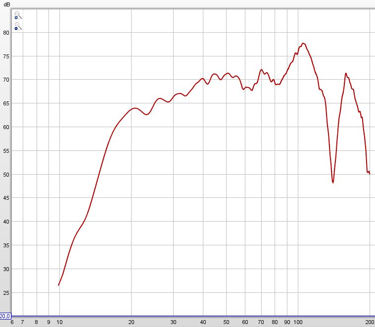
At least the last simulation looks close compared to the measurement I took from the clones I buit (uncalibrated ground plane measurement in the garden, mic. approx. 8m distance to mouth):
So, what do you think?
BR.
thanks for sharing that valuable drawing and the hornresp export file.
I just took a closer look to them and have some questions:
The export file contains dimensions which are VERY different compared to the PDF file. I also noticed that the TSP in the export file are different to those in TB's spec sheet.
This is the data from your hornresp export file:
An externally hosted image should be here but it was not working when we last tested it.
Based on the dimensions from your PDF and the TSP from TB's spec sheet the input parameters look like this:
Corresponding to your hornresp export file:
An externally hosted image should be here but it was not working when we last tested it.
Consequently the results of the sim look very different:
This is based on the data from your hornresp export file:
An externally hosted image should be here but it was not working when we last tested it.
And this is based on the dimensions from your PDF and the TSP from TB's spec sheet
An externally hosted image should be here but it was not working when we last tested it.
Or am I missing someting?
At least the last simulation looks close compared to the measurement I took from the clones I buit (uncalibrated ground plane measurement in the garden, mic. approx. 8m distance to mouth):
An externally hosted image should be here but it was not working when we last tested it.
So, what do you think?
BR.
Hi Volvotreter,
Post #144: "...So, what do you think?..."
The T/S data came from mwmkravchenko. I don't have any way to verify the data, maybe you have measured T/S for the TB W8-8740P? (I'm also fighting w/ a recently "updated" to Windows 10 laptop. MS is nuts.)
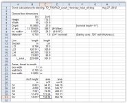
At the moment I don't have a lot of free time, but I revisited the spreadsheet I used to convert/calculate the Hornresp Input data. The main difference is that I used .709" wall thickness in the calculations, otherwise the areas and length seem to be correct?
Regards,
Post #144: "...So, what do you think?..."
The T/S data came from mwmkravchenko. I don't have any way to verify the data, maybe you have measured T/S for the TB W8-8740P? (I'm also fighting w/ a recently "updated" to Windows 10 laptop. MS is nuts.)
At the moment I don't have a lot of free time, but I revisited the spreadsheet I used to convert/calculate the Hornresp Input data. The main difference is that I used .709" wall thickness in the calculations, otherwise the areas and length seem to be correct?
Regards,
Attachments
Hi TB46
Mine are from a TB spec sheet. Now I checked the TB web site and surprisingly they show somewhat different TSP.
To the left is my (old) spec sheet, to the right is the one which is currently on the TB site:
Levc: HUGE difference, Q's and the suspension compliance are also somewhat different. Sadly I have not measured mine.
The comparing simulation shows a little difference (black = new data / grey = old data):
In the PDF (plan) there is the unfolded horn horn shown with dimensions. These are the dimensions I took.
The dimensions in the export file you posted 1st look odd to me. Their simulation
shows the rugged response and the dimensions are very different to your drawing.
And I trust your drawing...
I also simulated the Eminence 290-4008 driver referenced by brookhart995. This is what it looks like:
(black = Eminence / grey = W8-740P "old data")
Considering the price they are in the same ballpark. I cannot judge on which might be the better choice.
BR.
Hi Volvotreter,
Post #144: "...So, what do you think?..."
The T/S data came from mwmkravchenko. I don't have any way to verify the data, maybe you have measured T/S for the TB W8-8740P?
Mine are from a TB spec sheet. Now I checked the TB web site and surprisingly they show somewhat different TSP.
To the left is my (old) spec sheet, to the right is the one which is currently on the TB site:
An externally hosted image should be here but it was not working when we last tested it.
Levc: HUGE difference, Q's and the suspension compliance are also somewhat different. Sadly I have not measured mine.
The comparing simulation shows a little difference (black = new data / grey = old data):
An externally hosted image should be here but it was not working when we last tested it.
Yes this is really nuts. Win10 is calling home all the time...(I'm also fighting w/ a recently "updated" to Windows 10 laptop. MS is nuts.)
At the moment I don't have a lot of free time, but I revisited the spreadsheet I used to convert/calculate the Hornresp Input data. The main difference is that I used .709" wall thickness in the calculations, otherwise the areas and length seem to be correct?
In the PDF (plan) there is the unfolded horn horn shown with dimensions. These are the dimensions I took.
The dimensions in the export file you posted 1st look odd to me. Their simulation
shows the rugged response and the dimensions are very different to your drawing.
And I trust your drawing...
I also simulated the Eminence 290-4008 driver referenced by brookhart995. This is what it looks like:
An externally hosted image should be here but it was not working when we last tested it.
(black = Eminence / grey = W8-740P "old data")
An externally hosted image should be here but it was not working when we last tested it.
Considering the price they are in the same ballpark. I cannot judge on which might be the better choice.
BR.
@TB46
thanks for sharing that valuable drawing and the hornresp export file.
I just took a closer look to them and have some questions:
The export file contains dimensions which are VERY different compared to the PDF file. I also noticed that the TSP in the export file are different to those in TB's spec sheet.
This is the data from your hornresp export file:
An externally hosted image should be here but it was not working when we last tested it.
Based on the dimensions from your PDF and the TSP from TB's spec sheet the input parameters look like this:
Corresponding to your hornresp export file:
An externally hosted image should be here but it was not working when we last tested it....
So, what do you think?
BR.
I only have a couple of minutes right now and I'll look into this further tonight when I have more time.
BUT a quick look at the drawing in post 30 says Exit 1, Exit 2 and Exit 3 are all the same dimensions, roughly 9.5 x 14 inches. These 3 possible exit locations look like 3 mouth placement possibilities. 9.5 x 14 inches is approximately 133 sq inches, or 858 sq cm.
Therefore the sim that has S5 close to 858 has to be the correct one. The second sim has S5 at 356 sq cm which is way too small.
Like I said, I simulated this years ago and from what I remember tb46's results look pretty reasonable. This flare is close enough to a single flare rate single CON segment from S2 to S5 to get an idea of what's going on, so if you figure out the cross sectional area at S2 and S5 a very simple sim will show that tb46's results should be pretty close, I think.
Quick story while I have a couple of minutes ...
Back in 2008 or 2009 I wanted to build a tapped horn. This was shortly after Hornresp updated with ability to sim tapped horns. There were VERY few built and measured tapped horns at the time, I could only find 3 or 4 examples with plans and measurements to study. (Remember this was back when it was hotly debated that tapped horns couldn't be simulated properly.)
The TH_SPUD was one of the few examples that I could find plans and measurements for (both commercial and diy since the plans were already "leaked" way back then). So I studied the SPUD and made a tiny single driver version inspired by the SPUD with a tand band w6-1139. (Measured specs were considerably different than published.)
I emulated a similar wild and spiky response in mine.
I put very light stuffing in the first few feet of the horn. This can't be removed. This is an indoors mic in mouth measurement of the tapped horn with no stuffing in the mouth. You can see the predicted spike at 100 hz is almost completely killed by the stuffing. The tapped horn is the lower trace, dark green.
Now here's something very interesting. This is an outside measurement, measured at about 10 meters, with a good quantity of stuffing in the horn mouth going back about 18 inches from the mouth to the driver.
Compare that measurement to the sim. Just like Danley's measurements show, a simulated wild spiky simulated horn calms right down with a bit of stuffing in the throat and the mouth. The curve shape of this measurement is pretty similar to the curve shape of Danley's SPUD and DTS-10 measurements. Maybe this is a bit overstuffed, the huge predicted spike at 100 hz is completely gone now.
Relatively small amounts of stuffing make a big difference.
More info on this little tapped horn (including folded layout picture) here - https://sites.google.com/site/amateuraudio/projects-1/tapped-horn
Back in 2008 or 2009 I wanted to build a tapped horn. This was shortly after Hornresp updated with ability to sim tapped horns. There were VERY few built and measured tapped horns at the time, I could only find 3 or 4 examples with plans and measurements to study. (Remember this was back when it was hotly debated that tapped horns couldn't be simulated properly.)
The TH_SPUD was one of the few examples that I could find plans and measurements for (both commercial and diy since the plans were already "leaked" way back then). So I studied the SPUD and made a tiny single driver version inspired by the SPUD with a tand band w6-1139. (Measured specs were considerably different than published.)
I emulated a similar wild and spiky response in mine.
An externally hosted image should be here but it was not working when we last tested it.
I put very light stuffing in the first few feet of the horn. This can't be removed. This is an indoors mic in mouth measurement of the tapped horn with no stuffing in the mouth. You can see the predicted spike at 100 hz is almost completely killed by the stuffing. The tapped horn is the lower trace, dark green.
An externally hosted image should be here but it was not working when we last tested it.
[/QUOTE]Now here's something very interesting. This is an outside measurement, measured at about 10 meters, with a good quantity of stuffing in the horn mouth going back about 18 inches from the mouth to the driver.
An externally hosted image should be here but it was not working when we last tested it.
Compare that measurement to the sim. Just like Danley's measurements show, a simulated wild spiky simulated horn calms right down with a bit of stuffing in the throat and the mouth. The curve shape of this measurement is pretty similar to the curve shape of Danley's SPUD and DTS-10 measurements. Maybe this is a bit overstuffed, the huge predicted spike at 100 hz is completely gone now.
Relatively small amounts of stuffing make a big difference.
More info on this little tapped horn (including folded layout picture) here - https://sites.google.com/site/amateuraudio/projects-1/tapped-horn
Last edited:
Hi just a guy,
your're indeed right. I misinterpreted TB46's drawing . These should be the right input parameters:
Wit these parameters the comparing simulation of new vs. old TSP shows (again) a little difference (black = new data / grey = old data):
And the Eminence in question
compared to the W8-740P (black = Eminence / grey = W8-740P "old data")
That a peaky response can be smoothed with stuffing, as you're saying, is then supported here as well since the ones I built measure also smoother than the simulation without stuffing predicts.
BR.
your're indeed right. I misinterpreted TB46's drawing
. These should be the right input parameters:An externally hosted image should be here but it was not working when we last tested it.
Wit these parameters the comparing simulation of new vs. old TSP shows (again) a little difference (black = new data / grey = old data):
An externally hosted image should be here but it was not working when we last tested it.
And the Eminence in question
An externally hosted image should be here but it was not working when we last tested it.
compared to the W8-740P (black = Eminence / grey = W8-740P "old data")
An externally hosted image should be here but it was not working when we last tested it.
That a peaky response can be smoothed with stuffing, as you're saying, is then supported here as well since the ones I built measure also smoother than the simulation without stuffing predicts.
BR.
I did see that all TH do respond badly on passive crossovers. I do not now if this also happens in reality, but it seems I need a real sub amplifier with active crossover, the it is really easy to put advanced filering and get things flat.
This is also true for other kinds of subs like the T-TQWT who do better on aktive amp.
regards
This is also true for other kinds of subs like the T-TQWT who do better on aktive amp.
regards
Hi Volvotreter,
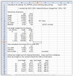
Good that we found agreement on the numbers.") I'll just summarize my posts on this subject here, and add another spreadsheet screenprint, this time w/ .720" wall thickness.
I'll just summarize my posts on this subject here, and add another spreadsheet screenprint, this time w/ .720" wall thickness.
Post #140: Hornresp Export file
Post #141: Referenced drawing pdf
Post #145: Spreadsheet for Hornresp Input data - wall: .709"
here: Spreadsheet for Hornresp Input data - wall: .720"
At the very least this should give somebody a good start into AkAbak (using Hornresp Export-AkAbak Script).
Regards,
Good that we found agreement on the numbers.
I'll just summarize my posts on this subject here, and add another spreadsheet screenprint, this time w/ .720" wall thickness.Post #140: Hornresp Export file
Post #141: Referenced drawing pdf
Post #145: Spreadsheet for Hornresp Input data - wall: .709"
here: Spreadsheet for Hornresp Input data - wall: .720"
At the very least this should give somebody a good start into AkAbak (using Hornresp Export-AkAbak Script).
Regards,
Attachments
- Status
- This old topic is closed. If you want to reopen this topic, contact a moderator using the "Report Post" button.
- Home
- Loudspeakers
- Subwoofers
- Dual 8" tapped horn = TH-SPUD