Hornresp Update 5400-220706
Hi Everyone,
BUG FIX
The bug identified in Post #12,771 has now been fixed.
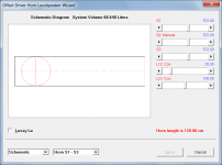
Given L12 = 20.00 cm and L23 = 100.00 cm:
Attachment 1 shows the L12 + L23 horn length incorrectly as 120.10 cm before the fix.
Attachment 2 shows the L12 + L23 horn length correctly as 120.00 cm after the fix.
My thanks to GM for reporting the problem.
Kind regards,
David
Hi Everyone,
BUG FIX
The bug identified in Post #12,771 has now been fixed.
Given L12 = 20.00 cm and L23 = 100.00 cm:
Attachment 1 shows the L12 + L23 horn length incorrectly as 120.10 cm before the fix.
Attachment 2 shows the L12 + L23 horn length correctly as 120.00 cm after the fix.
My thanks to GM for reporting the problem.
Kind regards,
David
Attachments

Hi and thanks to all of you.
Is possible to pass on to the filter wizard after filling options applied?
Because i get this error when doing that:

If i do not apply filling i can get the filter wizard running, same record. Something wrong in the record or in my sequence use of HR features ?
Is possible to pass on to the filter wizard after filling options applied?
Because i get this error when doing that:
If i do not apply filling i can get the filter wizard running, same record. Something wrong in the record or in my sequence use of HR features ?
Attachments
I found this problem discussed here: https://www.diyaudio.com/community/threads/hornresp.119854/post-6333381
I deleted all hr files, reinstalled last version and imported the record from BSteele boxplan mltl3.
Same error in opening filter wizard after applying filling, no error without filling. Is there anything to do after applying filling and before
going to filter wizard? Thank you, all.
Record imported:
ID=BOXPLAN
Ang=2.0 x Pi
Eg=15
Rg=0,1
Fta=0
S1=626,9
S2=526,9
Par=44,9
F12=0
S2=526,9
S3=460,7
Par=29,9
F23=0
S3=460,7
S4=352
Par=49,1
F34=0
S4=352
S5=352
Par=32,3
F45=0
Sd=550
Bl=25,15
Cms=0,000151
Rms=4,96
Mmd=59,68
Le=0,75
Re=5,1
OD=1
Vrc=0
Lrc=0
Ap1=0
Lp=0
Vtc=0
Atc=0
Pmax=700
Xmax=7,5
Path=52
Mass=0
Re'=0
Leb=0
Le=0
Ke=0
Rss=0
Rms=0
Ams=0
Comment=BOXPLAN-MLTL3 1.3 BETA - 2022-07-09 400x350x800
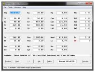
Same record exported by HR:
ID=48.20
Ang=2.0 x Pi
Eg=15.00
Rg=0.10
Fta=0.00
S1=626.90
S2=526.90
Par=44.90
F12=0.00
S2=526.90
S3=460.70
Par=29.90
F23=0.00
S3=460.70
S4=352.00
Par=49.10
F34=0.00
S4=352.00
S5=352.00
Par=32.30
F45=0.00
Sd=550.00
Bl=25.15
Cms=1.51E-04
Rms=4.96
Mmd=59.68
Le=0.75
Re=5.10
OD=1
Vrc=0.00
Lrc=0.00
Ap1=0.00
Lp=0.00
Vtc=0.00
Atc=0.00
Pmax=700
Xmax=7.5
Path=52.0
Mass=0.00
Re'=0.00
Leb=0.00
Le=0.00
Ke=0.00
Rss=0.00
Rms=0.00
Ams=0.00
Fr1=0.00
Fr2=0.00
Fr3=0.00
Fr4=0.00
Tal1=100
Tal2=100
Tal3=100
Tal4=100
Comment=BOXPLAN-MLTL3 1.3 BETA - 2022-07-09 400x350x800
I deleted all hr files, reinstalled last version and imported the record from BSteele boxplan mltl3.
Same error in opening filter wizard after applying filling, no error without filling. Is there anything to do after applying filling and before
going to filter wizard? Thank you, all.
Record imported:
ID=BOXPLAN
Ang=2.0 x Pi
Eg=15
Rg=0,1
Fta=0
S1=626,9
S2=526,9
Par=44,9
F12=0
S2=526,9
S3=460,7
Par=29,9
F23=0
S3=460,7
S4=352
Par=49,1
F34=0
S4=352
S5=352
Par=32,3
F45=0
Sd=550
Bl=25,15
Cms=0,000151
Rms=4,96
Mmd=59,68
Le=0,75
Re=5,1
OD=1
Vrc=0
Lrc=0
Ap1=0
Lp=0
Vtc=0
Atc=0
Pmax=700
Xmax=7,5
Path=52
Mass=0
Re'=0
Leb=0
Le=0
Ke=0
Rss=0
Rms=0
Ams=0
Comment=BOXPLAN-MLTL3 1.3 BETA - 2022-07-09 400x350x800
Same record exported by HR:
ID=48.20
Ang=2.0 x Pi
Eg=15.00
Rg=0.10
Fta=0.00
S1=626.90
S2=526.90
Par=44.90
F12=0.00
S2=526.90
S3=460.70
Par=29.90
F23=0.00
S3=460.70
S4=352.00
Par=49.10
F34=0.00
S4=352.00
S5=352.00
Par=32.30
F45=0.00
Sd=550.00
Bl=25.15
Cms=1.51E-04
Rms=4.96
Mmd=59.68
Le=0.75
Re=5.10
OD=1
Vrc=0.00
Lrc=0.00
Ap1=0.00
Lp=0.00
Vtc=0.00
Atc=0.00
Pmax=700
Xmax=7.5
Path=52.0
Mass=0.00
Re'=0.00
Leb=0.00
Le=0.00
Ke=0.00
Rss=0.00
Rms=0.00
Ams=0.00
Fr1=0.00
Fr2=0.00
Fr3=0.00
Fr4=0.00
Tal1=100
Tal2=100
Tal3=100
Tal4=100
Comment=BOXPLAN-MLTL3 1.3 BETA - 2022-07-09 400x350x800
Code:
~~~~~~~~~~~~~~~~~~~~~~~~~~~~~~~~~~~~~~~~~~~~~~~~~~~~~~~~~~~~~~~~~~~~~~~~~~~~~~~~~
FILTER
      0   0.01    0.0     -1      0   0.01    0.0     -1      0   0.01    0.0     -1
      0   0.01    0.0     -1      0   0.01    0.0     -1      0   0.01    0.0     -1
    0    0    0    0
  1  30.50.5
  00.50.50.5
SSSS
0111
1011
0022
1111
111
000
~~~~~~~~~~~~~~~~~~~~~~~~~~~~~~~~~~~~~~~~~~~~~~~~~~~~~~~~~~~~~~~~~~~~~~~~~~~~~~~~~At the moment of the switch to filter wizard, yes Fr1-2 were not empty fields.Have you tried it with some value in Fr1 - 4?
But even if i load the same record with Fr1-2 values already in (record file edited), same error.
I found a limit in Fr values here, at least with this record.
If i set values > 600 in Fr1-2 i get the overflow error. I did not try any possible number but till 600 is good, i can
go on to the filter wizard and continue the simulations...... greater values as 650, 675, 700, 800 -> error overflow
If i set values > 600 in Fr1-2 i get the overflow error. I did not try any possible number but till 600 is good, i can
go on to the filter wizard and continue the simulations...... greater values as 650, 675, 700, 800 -> error overflow
Is possible to pass on to the filter wizard after filling options applied?
Because i get this error when doing that:
Hi deepboy,
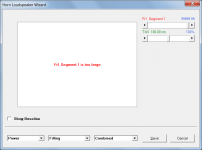
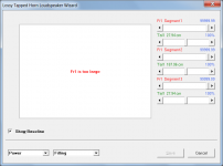
The absorbent filling material model used in Hornresp is a very good one, but it breaks down mathematically at high frequencies and under certain conditions can also become inaccurate at lower frequencies, due to numerical overflows and underflows. There is nothing that can be done about this, it all depends upon the segment geometry and the Fr1 and Tal1 values specified for that segment. Rather than producing inaccurate results, the Loudspeaker Wizard generates an advisory message instead, as shown in the attachment.
To reduce the chances of the model breaking down, Loudspeaker Wizard charts are limited to a maximum frequency of 2000 Hz when absorbent filling material is specified. The Filter Wizard currently does not have this same constraint.
In your original example the absorbent filling material model breaks down at a frequency higher than 2000 Hz. This is outside the frequency range of the Loudspeaker Wizard so the results it shows are valid, but when the Filter Wizard is then selected it considers frequencies up to 20000 Hz and sees the overflow, thus generating the run-time error message.
Thanks for bringing this problem to my attention, it will be fixed in the next update.
Kind regards,
David
Attachments
Changing L12 and L23 from Par to Con will enable larger values of Fr1 to be used for segments 1 and 2.greater values as 650, 675, 700, 800 -> error overflow
Hi David -- Another thing I keep forgetting to ask if you have a minute to look.
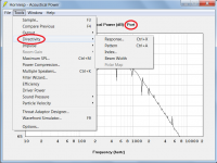
CH1 O(F)P's: Would it be a big pain to try to flip the "Port" and "Horn 2" outputs selected in the Tools->Output menu? We can get directivity, pressures etc. for the "Horn 2" but the output is actually the port so it'd be more useful the other way (though I admit looking at port output spectrograms has been interesting). Alternatively, maybe enabling the calcs for both outputs is easier?
Here's a wizarded CH I chopped into a CH1OP as an example case just to show the outputs flipped.
Thanks for looking and for all you do!
Hi deepboy,
The absorbent filling material model used in Hornresp is a very good one, but it breaks down mathematically at high frequencies and under certain conditions can also become inaccurate at lower frequencies, due to numerical overflows and underflows. There is nothing that can be done about this, it all depends upon the segment geometry and the Fr1 and Tal1 values specified for that segment. Rather than producing inaccurate results, the Loudspeaker Wizard generates an advisory message instead, as shown in the attachment.
To reduce the chances of the model breaking down, Loudspeaker Wizard charts are limited to a maximum frequency of 2000 Hz when absorbent filling material is specified. The Filter Wizard currently does not have this same constraint.
In your original example the absorbent filling material model breaks down at a frequency higher than 2000 Hz. This is outside the frequency range of the Loudspeaker Wizard so the results it shows are valid, but when the Filter Wizard is then selected it considers frequencies up to 20000 Hz and sees the overflow, thus generating the run-time error message.
Thanks for bringing this problem to my attention, it will be fixed in the next update.
Kind regards,
David
I can attest to the model being robust working last year on a few maximally damped enclosures that simulated pretty close to their actual measurements.
Hi grindstone,We can get directivity, pressures etc. for the "Horn 2" but the output is actually the port so it'd be more useful the other way
I have had a quick look, and with a bit of work I think that it should be possible to give you Directivity Response, Pattern, Index and Beam Width for the port, but not Polar Map, which would require just too many coding changes. Would this be okay?
The Horn 2 Directivity tools would remain as they currently are.
Kind regards,
David
Attachments
Hi Mark,I can attest to the model being robust working last year on a few maximally damped enclosures that simulated pretty close to their actual measurements.
That is good to know. Thanks for the feedback.
Kind regards,
David
I think I may have come up with a sneaky way to include the Polar Map as wellbut not Polar Map
") . If all goes according to plan, hopefully everything will be in the next update.
. If all goes according to plan, hopefully everything will be in the next update.Hi hi,
I have this tapped horn and I'd like to try to make a somewhat equivalent version by extending the fold path taller and slimming the depth to 20cm. I was wondering if someone could help me simulate it? I'm not highly experienced with horn resp although I've had at it a few times. I seem to get some plots going well enough but am not fully confident enough yet in the results. This is the Mivoc 10" tapped horn.
Thanks!
Attachments
Here is where I have landed. Very much still trying to figure this out..
S1 = the horn throat which I'm looking at as a letter box, sort of..
So S1= the cross sectional area of the first piece of wood where the cone almost couples to the plywood ( for a tapped horn config )
S2 is the cross sectional area for the exit for the letterbox
L12 is simply the throw between said cross sectional areas
S3 is the cross sectional area that is actually the rock bottom start of the true horn path
S4 is the end of the first conical flare
L34 is the throw between the bottom of the horn and said end of the first conical flare
S5 is the cross sectional area of the horn mouth
L45 is the throw from between S4 and S5
How bad am I messing up?
Hornresp Update 5400-220725
Hi Everyone,
CHANGE 1
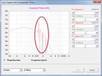
The Loudspeaker Wizard now detects when the absorbent filling material model begins to break down and displays the "Fr1 is too large" message at that point rather than waiting for a numerical overflow or underflow calculation error to actually occur.
Attachment 1 shows how the power response can be corrupted as the model begins to break down. This erroneous result would previously have been displayed.
Attachment 2 shows the message that is now displayed at the point that the model begins to break down.
CHANGE 2
The Directivity tools can now be used with either Output 1 or Output 2, and are applicable to direct radiating single drivers, single passive radiators, finite single-segment non-negative flare horns with no throat adaptor, and non-negative flare ports. The Directivity tools sections in the Hornresp Help file have been updated accordingly.
Specifically, the Directivity tools now apply to the offset port in a CH1 system with closed mouth. Post #12,791 refers.
Also, the time it takes for the Directivity Polar Map to be calculated has been reduced in some cases by up to 70 percent.
NOTE - This change has been extensively tested but there are so many possible system configurations that something may have been missed. Could you please report any problems or inconsistencies found while using the new functionality.
BUG FIX
The bug identified in Post #12,782 has now been fixed. My thanks to deepboy for reporting the problem.
Kind regards,
David
Hi Everyone,
CHANGE 1
The Loudspeaker Wizard now detects when the absorbent filling material model begins to break down and displays the "Fr1 is too large" message at that point rather than waiting for a numerical overflow or underflow calculation error to actually occur.
Attachment 1 shows how the power response can be corrupted as the model begins to break down. This erroneous result would previously have been displayed.
Attachment 2 shows the message that is now displayed at the point that the model begins to break down.
CHANGE 2
The Directivity tools can now be used with either Output 1 or Output 2, and are applicable to direct radiating single drivers, single passive radiators, finite single-segment non-negative flare horns with no throat adaptor, and non-negative flare ports. The Directivity tools sections in the Hornresp Help file have been updated accordingly.
Specifically, the Directivity tools now apply to the offset port in a CH1 system with closed mouth. Post #12,791 refers.
Also, the time it takes for the Directivity Polar Map to be calculated has been reduced in some cases by up to 70 percent.
NOTE - This change has been extensively tested but there are so many possible system configurations that something may have been missed. Could you please report any problems or inconsistencies found while using the new functionality.
BUG FIX
The bug identified in Post #12,782 has now been fixed. My thanks to deepboy for reporting the problem.
Kind regards,
David
Attachments
The page linked below may help:Here is where I have landed. Very much still trying to figure this out..
https://www.diysubwoofers.org/th/
- Home
- Loudspeakers
- Subwoofers
- Hornresp