Hi Brian,(which I assume means that the import format has changed as well?).
The import format has not changed as far as files exported from BOXPLAN are concerned. It should be possible to import BOXPLAN files into Hornresp as before. One thing I just noticed though - the boxplan-tham.xls spreadsheet, as well as having the standard 'Export Sim' button, also has an 'Import Sim' button. What does the 'Import Sim' button do? Hopefully it is not trying to import a file exported from Hornresp.
Kind regards,
David
My preference would be for the spreadsheets to be changed to accept files that have the new format, if at all possible. If this cannot be done then a separate File > Export > BOXPLAN menu could perhaps be added to Hornresp to enable files to be exported using the old format. This would mean however that there would then be two different format types that could be exported (and therefore also imported), which might be confusing for some users.
Feature Suggestion - Ability to suggest a good TL design based on driver T/S parameters
Hello David,
Is it feasible for hornresp to provide a good first guess design based on the driver T/S parameters and the Martin King's alignment tables at http://www.quarter-wave.com/TLs/TL_Alignments.pdf ?
Hello David,
Is it feasible for hornresp to provide a good first guess design based on the driver T/S parameters and the Martin King's alignment tables at http://www.quarter-wave.com/TLs/TL_Alignments.pdf ?
Hi Giri,
I would need to see the alignment tables you are referring to before I could make a decision either way. If it meant constructing data sets containing hundreds of data points, then the answer is probably no, but I would really need to see the tables first to be sure.
Kind regards,
David
I would need to see the alignment tables you are referring to before I could make a decision either way. If it meant constructing data sets containing hundreds of data points, then the answer is probably no, but I would really need to see the tables first to be sure.
Kind regards,
David
Attachments
Hi GM,
The document Giri refers to was released in 2021 and makes use of alignment tables contained in Vance Dickason's Loudspeaker Design Cookbook. The document you attached is much older, having been released in 2006. I was able to download a copy of the .xls spreadsheet but the contents are protected and hidden, so it doesn't really tell me much.
If I was to do anything I would want to use the Vance Dickason tables rather than those contained in the superseded 2006 document. I don't have a copy of the Loudspeaker Design Cookbook so someone would have to provide the necessary information.
Kind regards,
David
That is good to know. If all else fails I can try using those tables. Did you assume fs for the tuning frequency, and did you offset the driver?the various combinations I simmed from his original produces excellent designs.
(I have now managed to find a copy of the required Vance Dickason alignment table online).
It's been a long time now, though for sure I used offset drivers since the focus was for MLTLs, but IIRC just calc'd a T/S max flat alignment to see what he came up with compared to mine, which were basically pretty close except mine were 'fatter' Vb wise and his had the vent at the bottom whereas mine would be at whatever harmonic that gave it the 'toe tappin'/'jumpin little juke joint' ") type performance typical of many vintage speakers and later known as the 'West Coast Sound' thanks to Altec/JBL.
type performance typical of many vintage speakers and later known as the 'West Coast Sound' thanks to Altec/JBL.
type performance typical of many vintage speakers and later known as the 'West Coast Sound' thanks to Altec/JBL.That is good to know. If all else fails I can try using those tables. Did you assume fs for the tuning frequency, and did you offset the driver?
(I have now managed to find a copy of the required Vance Dickason alignment table online).
The general rules of thumb given by Martin King were;
1) Tuning frequency is fs by default
2) If the Qts < 0.35, tune up a little from fs, and if Qts > 0.45, tune down a little from fs
3) Offset the driver to 1/3rd of the line length to suppress the first harmonic
3) Try to keep the volume equal to Vas
4) Tapering down and mass loading are techniques to reduce the line length
These rules have consistently given good simulations over the years. I hope this is of some help.
How about this...
Vb=20*Qts^3.3*Vas
Fb=(Vas/Vb)^0.31*Fs
L=8500/Fb
CSA=Vb*1000/L
Offset=0.341
S1=S2=S3=CSA
L12=Offset*L
L23=L-L12
The first two equations are for an optimized vented enclosure using the same driver.
The others just convert that optimized vented enclosure to an offset-driver TL of constant CSA, where the first harmonic resonance is nulled out by the position of the driver.
It should be possible to develop this even further (translate to a tapered TL) by taking the harmonic resonance as an input value and using that to determine the required taper to achieve Fb and that harmonic resonance.
Hi Giri, GM and Brian,
Thanks for all the information. It seems that we can get different answers depending on which set of rules we choose to adopt.
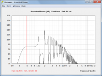
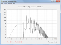
I have compared Martin's 2006 and 2021 methods and it seems that the 2006 method produces the better results. With the same driver, taper rate of 0.2 and no driver offset, Attachment 1 shows the result obtained using the 2006 method and Attachment 2 shows the result obtained using the 2021 method.
Interestingly, in working through the 2021 paper I think that I may have found an error. Martin calculates the taper volume using the formula:
Vb = 0.5 * (S0 + SL) * L
This assumes that the cross-sectional area tapers linearly, but it is the radius, not the area, that actually tapers linearly. The correct formula to use for an axisymmetric conical segment is:
Vb = Pi * L * (R0 ^ 2 + R0 * RL + RL ^ 2) / 3
Kind regards,
David
Thanks for all the information. It seems that we can get different answers depending on which set of rules we choose to adopt
.I have compared Martin's 2006 and 2021 methods and it seems that the 2006 method produces the better results. With the same driver, taper rate of 0.2 and no driver offset, Attachment 1 shows the result obtained using the 2006 method and Attachment 2 shows the result obtained using the 2021 method.
Interestingly, in working through the 2021 paper I think that I may have found an error. Martin calculates the taper volume using the formula:
Vb = 0.5 * (S0 + SL) * L
This assumes that the cross-sectional area tapers linearly, but it is the radius, not the area, that actually tapers linearly. The correct formula to use for an axisymmetric conical segment is:
Vb = Pi * L * (R0 ^ 2 + R0 * RL + RL ^ 2) / 3
Kind regards,
David
Attachments
Thinking about it some more I suspect that Martin is probably assuming a parabolic rather than a conical profile for the transmission line, which makes good sense. In that case the cross-sectional area changes linearly with length, and his volume formula will be correctInterestingly, in working through the 2021 paper I think that I may have found an error.
.Switching from Con to Par makes very little difference to the results shown above, though.
Thinks, while academically useful, I don't think anyone should really aim to build and end-loaded TL, due to the impact of the the 3*Fb harmonic on the passband of the TL. That's why I suggested an approach that produces an offset TL with a wider passband instead. Interestingly, you can change the exponent part of the equation for Vb a bit and still end up with an offset TL with a flat passband. For example, if you use Vb=20*Qts^3*Vas instead of Vb=20*Qts^3.3*Vas, you end up with a larger offset TL with a lower Fb.
If you can work out how to include taper then your model will most likely become the best that there is. Considering its relative simplicity compared to Martin's two models, it already produces very impressive results.It should be possible to develop this even further (translate to a tapered TL) by taking the harmonic resonance as an input value and using that to determine the required taper to achieve Fb and that harmonic resonance.
- Home
- Loudspeakers
- Subwoofers
- Hornresp