And to add an intrigue - there are mosfets currents: http://gaydenko.com/ab-dynamic/currents39.png
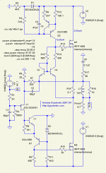
As shown at the schematics, Iq is about 210mA. With too low Iq derivation isn't so smooth around 0V. I think, Iq about 100-150mA will be acceptable. Will see.janneman said:Andrew,
This is pretty intriguing! I guess the Iq is aroundf 50mA? Have you tried to run it with larger current, what would the transfer function look like then?
Do you know the open loop freq and phase response?
Jan Didden
dVout/sVin doesn't change with more amplitude of linear input signal: "all can happen already happened" inside +/-11V range
") Only a clipping at ~19V is outside the picture.
Only a clipping at ~19V is outside the picture.As for frequency prediction, I have found simulated results rather differ from reality for gnfb topologies. Moreover, you can see rather "strong" hf correction. At any case I'm not a fanatic of using instrumental amps for listening to a music
Hi Andrew
Interesting way to drive a quasi fet output stage. Very asymmetrical, even for quasi. There are members here who chastise asymmetrical topologies, but not me. I believe choice of components is more important, depending on goal of the circuit. The input j-fet is cascoded and keeps 5-6 Vds. This is good, and no need for matching because there is only one. I do have one question, do you think there would be need to have an active turn off device for M2 instead of R7 even though it appears to never turn completely off, but operates as class AB, or some type of totem pole buffer to drive the gate capacitance? How is capacitive loading for a sqare wave look at that 2KHz? And 10KHz?
Interesting way to drive a quasi fet output stage. Very asymmetrical, even for quasi. There are members here who chastise asymmetrical topologies, but not me. I believe choice of components is more important, depending on goal of the circuit. The input j-fet is cascoded and keeps 5-6 Vds. This is good, and no need for matching because there is only one.
I do have one question, do you think there would be need to have an active turn off device for M2 instead of R7 even though it appears to never turn completely off, but operates as class AB, or some type of totem pole buffer to drive the gate capacitance? How is capacitive loading for a sqare wave look at that 2KHz? And 10KHz?I have tried CC-follower between R7 and R18 - at least in simulation all the amp seems to be closer to oscillatorCBS240 said:Hi Andrew
Interesting way to drive a quasi fet output stage. Very asymmetrical, even for quasi. There are members here who chastise asymmetrical topologies, but not me. I believe choice of components is more important, depending on goal of the circuit. The input j-fet is cascoded and keeps 5-6 Vds. This is good, and no need for matching because there is only one.
Moreover, I have two amps with 560 and 680 ohm resistors at similar places with the same mosfets - both works fine.As for square waves, at first, there isn't any difference which frequency we use to test. A rise or fall time period does mean only. At any case, the amp is sufficiently fast to work with sound - just from experience.
As I have mentioned above, I don't think we must use instrumental amplifiers for music listening. Say, -120db, 100MHz, 100V/uS or such numbers mean nothing. At first message I have listed few demands I consider to be important for audio amplifier, if we say about a schematics only, omitting realization (PS, PCB and so on) details. I can add monotonically falling spectrum as another demand - while increasing harmonics number or lowering signal level. Plus small spectrum dependency from frequency.
anli said:Aha... Silence... The idea is perfect, and the realization via the schematics is beyond any criticism...
da,
we were waiting from 2005 on your update,
so do not be surprised of the silence, everybody hard thinks.

It is hard to me to make some interesting comments,
please explain what parts should be matched (if any),
congratulations!
Sorry, my fault... But... what do you mean?padamiecki said:da,
we were waiting from 2005 on your update,
Regulations were mentioned above. For two channels, probably, input fets must not be too different. A fet - current source must be able to generate ~4mA. Currently I don't see something else. Just want to repeat, the project isn't soldered yet - just design. But parts are ordered.padamiecki said:please explain what parts should be matched (if any),
anli said:
Sorry, my fault... But... what do you mean?
what fault? I am far from indicate someone's fault, there was no fault at all.
first time you showed similar project long time ago, and promissed finalize it. From your description I read that the sound did not make fatigue during listening and was fully detailed. I just could not be patient to wait for so long! As I remember you had even PCB for this project! This was good training for me waiting for your ready project.
Maybe before you wrote about another amp?

anli said:A fet - current source must be able to generate ~4mA.
This is exacly what I asked!
Anyway, the design is clever, I like it!
Thanks!
Hm... There was somebody else rather mepadamiecki said:first time you showed similar project long time ago
I have not another similar projects. And I didn't see such dynamic load regulation as have suggested here...anli said:
Hm... There was somebody else rather me
Anli, sorry, I had to mismatched you with someone else who used the same circuit software

Or slightly simplified jfet version with the same parameters:
http://gaydenko.com/ab-dynamic/schematics55.png
http://gaydenko.com/ab-dynamic/schematics55.png
anli said:Or slightly simplified jfet version with the same parameters:
Anli
I wish your thread and design will be more popular,
design is worth it!
Thanks for such kind words! At any case, I have no illusions and understand, non-standard schematics and (is more important) motivations are difficult for acceptancepadamiecki said:
Anli
I wish your thread and design will be more popular,
design is worth it!
Our mind is commonly ruled by plenty of "known things". Are these things right indeed? - this is another question and another story I really like your 49 circuit (cascoded 2sj103 as input-voltage gain stage). Isn't the transconductance of 2SJ103 a bit low? What is the open loop gain of the amp ? I wonder what BJT would be good as a buffer (X5) since M2 has a very big capacitance working in the "common source" mode. Also it seems to me that R16/X2/X4 are controlling the M1 in the similar way as it is done in NP's Aleph CCS (correct me if I'm wrong). Maybe it would be better to take a voltage sample from X5?
Anyway, I would love to see this project done, it could be a good sounding V-MOSEFT without 10 kg heatsinks.
Please keep us informed on progress of this amp !
Anyway, I would love to see this project done, it could be a good sounding V-MOSEFT without 10 kg heatsinks.
Please keep us informed on progress of this amp !
Probably another jfet may be used, but I have 2SJ103juma said:I really like your 49 circuit (cascoded 2sj103 as input-voltage gain stage). Isn't the transconductance of 2SJ103 a bit low? What is the open loop gain of the amp ? I wonder what BJT would be good as a buffer (X5) since M2 has a very big capacitance working in the "common source" mode. Also it seems to me that R16/X2/X4 are controlling the M1 in the similar way as it is done in NP's Aleph CCS (correct me if I'm wrong). Maybe it would be better to take a voltage sample from X5?
Anyway, I would love to see this project done, it could be a good sounding V-MOSEFT without 10 kg heatsinks.
Please keep us informed on progress of this amp !
The fet is loaded with "current source" (Ube/R5), and such load defines stage gain. Open loop gain depends on instant DC value. I don't remember values as am not interested in it
All Xn bjt are 2SA970/2SC2240 wrapped with few elements to simulate thermodynamic ("memory") distortions. It is done like here: http://gaydenko.com/spectrum/case03/schematics.png - left schematics.
As Vce is small for X5, 2SC2240 is suitable here.
I have not digged in Aleph (one of my aims is to get DC amp, which I have achieved
) and didn't understand what do you mean saying about "voltage sample from X5". M2 is N-channel also. Will you explain more detailed? R16/X2/X4 tries to keep M2 Id at constant level, and R16 is this current sensor.
BTW, such dynamic load may be used at any way, say, this is a simple follower draft (with -40db for 2d (highest) harmonic):
http://gaydenko.com/ab-dynamic/cdcd01.png
Here the main idea is presented more clear.
Currently most probable variant to be soldered is schematics55 rather 49.
Thanks, it's more clear now. My remark about similarity with Aleph is only in context of "modulating" a CCS (with some ~ current or voltage) which is a very old technique (White Cathode Follover). Anyway, that's not crucial in your circuit. What appeals to me is nice solution of thermal problems with V-MOSFETS and class AB artefacts. Also, some previous experience (and gut feeling) tells me that this amp (sch.49) should really sound good.
Please, share the impressions when you finish this project. Thanks !
Please, share the impressions when you finish this project. Thanks !
- Status
- This old topic is closed. If you want to reopen this topic, contact a moderator using the "Report Post" button.
- Home
- Amplifiers
- Solid State
- AB-dynamic