I was forced to choose between mosfets current stabilty and output drift stability. At current variant mosfets' current changes ~5-8% during warming up, and output offset changes ~40-50mV (I don't remember exactly measured values nowDid you have problems with DC stability?
") ).
).It is more correct to say about R13*R6, and load, and M1 transfer characteristic ratios - just to make dynamic load able to supply current to load at positive period half. Absolute R13 value is in sync with R8.How did you determine the ratio between R10 and R13?
As for R10 - if you have found first picture descibing the idea, you can guess I have realized some kind of hooliganism - Vgs and R10 are used to provide a (pseudo-constant) current of left bjt used as diod. This step was done in favour of simplicity, and R10 value was selected experimentally.
Last edited:
Good luck! Will be glad to know your listening experience.Thanks for the information, anli. I`m just curious about the thermal stability of your arrangement. I am going to make experiments with some hard-to-tame vertical MOSFETs in a few weeks.
It's funny, dynamic load (M1 and around) demands on using of vertical rather lateral "for audio" mosfets: initial Vgs must be rather high to take "voltage air" for X2,X4.
BTW, R10 (instead of CCS) "softens" NFB existing in the dynamic load itself - M1 transfer characteristic (dI/dV) is limited, and, as a result X2 current is mdulated by Vgs, slightly reducing dynamic load's NFB loop gain. It is, probably last "most secret place" in the schematics
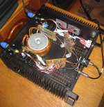
About thermostability, more strictly - about thermoenviroment. If you have looked at a picture with showing the amplifier inside, you, probably, noticed uncommon realization details. Among others (say, frontal input RCA connectors), you can see, I have rejected common practice to mount pcb to heatsink. I'm strongly sure, low-current details (i.e. placed on PCB) must be far from heartsinks. Top and bottom case's plates perforation serv this aim also.
Attachments
Member
Joined 2009
Paid Member
- Status
- This old topic is closed. If you want to reopen this topic, contact a moderator using the "Report Post" button.