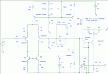
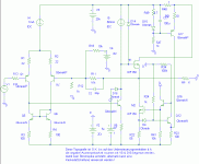
Cascoded JFET is a nice sounding combination. In sch49 X5 is separately cascoded and nicely linearised. Sch49 should have less OLG and less NFB. It might simulate worse, but it should sound better.
In sch55 J1 and X1 are forming a CFP-like arangement which is cascoded by Q1. The big V-MOSFET M2 might not be totally happy with drive from Q1 (I think that X5 in sch 49 does better job).
Anyway, it is easy enough to try both input configurations when you build the amp.
Best regards !
In sch55 J1 and X1 are forming a CFP-like arangement which is cascoded by Q1. The big V-MOSFET M2 might not be totally happy with drive from Q1 (I think that X5 in sch 49 does better job).
Anyway, it is easy enough to try both input configurations when you build the amp.
Best regards !
Hi Anli,
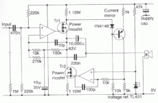
A class-AB bipolar amplifier arrangement was published in WW/EW about 12 years ago where the current in one half was sensed such that the other half maintained it at about 100mA; but both halves were driven.
In your circuit only the bottom half is driven, whilst the other voltage senses current and generates current correction. Thus the M1 half cannot react to back-EMF induced load current variation until the voltage sensing NFB loop controls M2. That is two gate capacitance 'filters' in series at high AF within the closed load-damping loop.
It might be worth looking at the output terminal damping characteristic, or simulating with an equivalent loudspeaker load at 10kHz.
Cheers ........ Graham.
juma,juma said:Cascoded JFET is a nice sounding combination. In sch49 X5 is separately cascoded and nicely linearised. Sch49 should have less OLG and less NFB. It might simulate worse, but it should sound better.
In sch55 J1 and X1 are forming a CFP-like arangement which is cascoded by Q1. The big V-MOSFET M2 might not be totally happy with drive from Q1 (I think that X5 in sch 49 does better job).
Anyway, it is easy enough to try both input configurations when you build the amp.
Best regards !
Let's see how the jfet "see world". Drain current is defined by 0.67V/R5 for sch49 and 0.67V/R6 for sch55. Drain voltage is -6.2V + 0.67V for sch49 and -6.2V + 0.67V*2 for sch55. You see, "jfet environments" are similar. As for driving M2 - I already soldered two amps with similar mosfet driving and have not noticed any problems - from measuring and ears POVs
At any case - you are right, listening test is needed.
BTW, the only aim of sch49/Q2 is to make better psrr of bottom power rail. In sch55 psrr is more "inherent"
Graham Maynard said:Hi Anli,
A class-AB bipolar amplifier arrangement was published in WW/EW about 12 years ago where the current in one half was sensed such that the other half maintained it at about 100mA; but both halves were driven.
In your circuit only the bottom half is driven, whilst the other voltage senses current and generates current correction. Thus the M1 half cannot react to back-EMF induced load current variation until the voltage sensing NFB loop controls M2. That is two gate capacitance 'filters' in series at high AF within the closed load-damping loop.
It might be worth looking at the output terminal damping characteristic, or simulating with an equivalent loudspeaker load at 10kHz.
Cheers ........ Graham.
Graham,
I have tried to load with a load capacitor only (1.3uF at 20KHz) and without load at all. At both cases I have not noticed any artifacts.
You are right, the amp output resistance is slightly different for top and bottom halves. It is clear form the transfer derivation http://gaydenko.com/ab-dynamic/transfer39.png I still have not found simple way to make top and bottom "more equal". OTOH, I have not any information about psychoacoustics results saying we must (or must not) have this or that output resistance behaving. And, on the third
Ordered parts are partly arrived, and I hope, the rest will arrive soon.
I like those circuits where only one half is driven and the other one is controlled by a current-feedback loop. There was once a suggestion for such a topology in the circuit ideas section of EW+WW. It used OP-AMPS though. I personally don't see a problem with such topologies and I did some simulations as well some time ago. I didn't build it so far however.
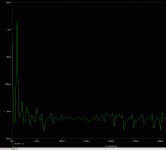
Below you can see the output spectrum of it if driven 12 dB below full output. 2nd order is dominant and approx 120 dB below fundamental. It is only a simulation of course and I am aware of its limited validity.
Regards
Charles
Below you can see the output spectrum of it if driven 12 dB below full output. 2nd order is dominant and approx 120 dB below fundamental. It is only a simulation of course and I am aware of its limited validity.
Regards
Charles
Attachments
phase_accurate,
Indeed, it is possible to add "full-featured" preamp, use OPAmps, and so on. Output stage itself (more strictly, dynamic load itself), as illustrated here http://gaydenko.com/ab-dynamic/cdcd01.png , is simple and self-contained, and is ready to be used at any topology Nevertheless, I'd like to try as simple the main idea realization (whole amp), as possible, but fulfilling demands listed at first post.
Indeed, it is possible to add "full-featured" preamp, use OPAmps, and so on. Output stage itself (more strictly, dynamic load itself), as illustrated here http://gaydenko.com/ab-dynamic/cdcd01.png , is simple and self-contained, and is ready to be used at any topology
Aha, I see.phase_accurate said:Hi Anli
I am not talking about the preamp section. The circuit used op-amps for the voltage-drive of one of the output devices and one for the underlying current loop. So the potential output voltage range was quite restricted.
Regards
Charles
I also find the whole idea of an output stage where the output devices never turn off very appealing.
I posted my thoughts on a circuit a few years ago, with the intention of running the output stage with a standing 50 - 100mA.
http://www.diyaudio.com/forums/showthread.php?s=&threadid=61120
and more recently seen similar idea on the following web site.
http://www.angelfire.com/ab3/mjramp/amp01.html
I posted my thoughts on a circuit a few years ago, with the intention of running the output stage with a standing 50 - 100mA.
http://www.diyaudio.com/forums/showthread.php?s=&threadid=61120
and more recently seen similar idea on the following web site.
http://www.angelfire.com/ab3/mjramp/amp01.html
I do not have to hand the bipolar circuit I mentioned above, but this might be the op-amp driven one you mention Charles.
Does
http://gaydenko.com/ab-dynamic/schematics01-idea.png
not show M1 turning off, which must inevitably lead to some form of crossover distortion when loudspeaker load currents lead voltage ?
Cheers .......... Graham.
Does
http://gaydenko.com/ab-dynamic/schematics01-idea.png
not show M1 turning off, which must inevitably lead to some form of crossover distortion when loudspeaker load currents lead voltage ?
Cheers .......... Graham.
Attachments
Hi Symon,
That Angelfire link of yours is the other circuit I mentioned above.
Basically a full class-AB architecture, but only one half drops into class-B with the idea that class-A control is maintained in one constantly active half. Here both halves are driven, though again, I would consider what happens with reactive loudspeaker load connection.
If I remember correctly the author offered this circuit without Patent protection.
Cheers ........ Graham.
Graham Maynard said:... I would consider what happens with reactive loudspeaker load connection
Graham,
How to investigate (yet in sim) the issue except for capacitance load?
Below you can see the first incarnartion that I simulated (also without patent protection).
Because my simulator only supports 10 transistors in total I had to refrain to a dirty little trick. I used the voltage-controlled current-source G1 instead of a 2nd FET. It would not be that difficult however to derive a circuit that uses a FET and some auxiliary circuitry instead.
Bias is set with R16 and R17. The circuitry around Q9 is there to guarantee that there is always the predefined (bias-) current flowing accross both output devices.
The disadvantage is the series resistor at the output (well -sometimes a purely resistive and frequency-independant output impedance might not even be bad at all).
The second one that I simulated has some similarity to the circuit that Graham posted. I will post it afterwards.
Regards
Charles
Attachments
Hi Anli,
Via simulation I would null an output fundamental to watch how the amplifier responds to suddenly starting 10kHz sines when forward driven with a representative loudspeaker load, also observe swept amp/phase and suddenly starting 10kHz sine with the amplifier reverse driven through a resistor of say half or a quarter of the R of nominal LS impedance.
Everyone to their own however, or life would be boring.
Cheers .......... graham.
Graham,Graham Maynard said:... I would null an output fundamental to watch how the amplifier responds to suddenly starting 10kHz sines when forward driven with a representative loudspeaker load, also observe swept amp/phase and suddenly starting 10kHz sine with the amplifier reverse driven through a resistor of say half or a quarter of the R of nominal LS impedance...
Thanks, I see your directions now
Charles,phase_accurate said:Here is the second version....
Indeed, ideas are resembling. Too complicated to my taste, but, as Graham said,
Graham Maynard said:...Everyone to their own however, or life would be boring...
Have not yet tried tests suggested by Graham, but psrr vs frequency curves are here:
http://gaydenko.com/ab-dynamic/psrr55-top-vs-input.png
http://gaydenko.com/ab-dynamic/psrr55-bottom-vs-input.png
Sets are simulated for input shifts 0mV, 200mV, ..., 1V for top half and, accordingly, 0mV, -200mV, ..., -1V for bottom half, both starting from blue for 0mV.
http://gaydenko.com/ab-dynamic/psrr55-top-vs-input.png
http://gaydenko.com/ab-dynamic/psrr55-bottom-vs-input.png
Sets are simulated for input shifts 0mV, 200mV, ..., 1V for top half and, accordingly, 0mV, -200mV, ..., -1V for bottom half, both starting from blue for 0mV.
Graham Maynard said:also observe swept amp/phase
Graham,
For this (slightly modified) schematics
http://gaydenko.com/ab-dynamic/schematics59.png
I have uploaded suggested simulation result:
http://gaydenko.com/ab-dynamic/back-emf-sweep59.png
- AC source was inserted in serial with load resistor, while last one was reduced to 2 ohm (BTW, Z of my LS is never below 6.7 ohm
- M1 source voltage was observed,
- there are three gain/phase pairs for different input DC shifts (as we have DC amplifier): blue for -1V, green for 0V and red for +1V.
- it is easy to distinguish gain and phase, as all phases start with ~0 grad.
OK, what's next? It this picture optimistic? Which behaving, at your experience, is sufficient for an amp to sound good?
Hi Anli,
If one half is better than the other then the overall performance cannot exceed that of the lesser half.
You say you have taken voltage reading from M1 source - but that is not what a loudspeaker 'sees'. Did you apply the reverse drive at this point also ?
If your amplifier needs a choke then it should be part of your test, so your voltmeter and test current should be at the output terminal, not the NFB node.
If your amplifier will run without a choke in most applications then do so, and test the amplifier circuit without the choke.
You could have two 'red' output terminals, one with choke for electro-statics etc., and one direct for electro-magnetics etc.
The red trace shows a negative phase characteristic, which implies reactance within the global loop; possibly in one output half ?; though the damping figure for that half appears high throughout AF.
What's next ?
I would apply a suddenly starting 10kHz sine of say just 1V via 8R to the output terminal and watch how the amplifier controls for the first few uS. I would do a positive start and a negative start.
Does the output stage quickly catch the sudden current change, or does it oscillate, or is it slow to return close to zero before the waveform continues ?
Cheers ............ Graham.
- Status
- This old topic is closed. If you want to reopen this topic, contact a moderator using the "Report Post" button.
- Home
- Amplifiers
- Solid State
- AB-dynamic


