I do not mind...the oposite, i love to see that there are humans in the other side
of my comunications in the forum...but i perceive that is not very acceptable...people tolerate only...and there are folks that hate that "flexibility".
Well..we cannot be good for everyone...let's be good for our mates.
Beautifull wood behind the speaker...the speaker by itself is very nice...i like it with that nice stand to put it at our ears level (perfect in my point of view).
Well...those tweeters may unballance your speaker...but when we have not better solution...the solution we have will turn the better one!
Very old unit...nice unit...but i was thinking about the acoustic suspension...this rubber foam ring around the speaker diafragm....maybe very old too.... this is not so good....say..the agging effect over those things.
I know that some constructors used cloth...fabric dampened with special plastic material...other use fabric with rubber..even sinthetic rubber was used....is your "acoustic suspension ring" in order?
Related the bias diodes.... alike Doctor Leach...i prefer diodes...and using 4 units things turns even better...having one with a small trimpot in parallel to adjust.....some amplifiier can hold 4 diodes and a series resistance....and those multiple junctions work better than a transistor i think...well..this is a result of experience and practice.... maybe theory can be different.
Triple darlington used in output will hold six diodes...to "create" enougth bias to 6 transistors...each one hungry to "eat" more than 500 milivolts each one.... yes...i have tested triple darlington...problem is that they are easy to oscilate....and i am hardly afraid of that...in special is a hard problem related our responsabilities if we publish things that may oscilate easy....errors made by constructor, misadjustments, board capacitances and inductances can create enormous mess...reason why i use to run from triple darlington as fast as devil may run out from the cross sign
Theories are alike a "North" to me..but my real direction will be the results of real world experiences....in the theories, triple darlington are not eager to oscilate...but real life....hehe
I do not feel good just obbeying rules and reading theories..also i do not like to repeat things i have readed or listened as Pirate's parrot.... i love to conclude having insigths during experiences....this is more pleasant to me....and when i open my mouth...normally...i have tested before those things i am saying.
Soldering iron..is almost always hot..and i use it to answer my doubts... beeing this way, i think, better and faster.
regards,
Carlos
VBE multiplier circuit, was suggested because a political reason
There are people that has not that flexible thougths...people that do not like experiences and substitutions....as normal amplifier use VBE multiplier..and this one was not using...people would junk the schematic very fast because of that.
Not to loose those guys, just because they are rigid about those "needed" subcircuits, i have suggested the VBE multiplier as external optional circuit.
I am not using it....i prefer big heatsinks...but the diodes may work even better than my big heatsinks and VBE multiplier.
Just not to loose those folks...giving to them the chance to know the simple amplifier sonics and also giving to me the chance not to loose potential constructors feeling suspectious because of VBE multiplier absence.
regards,
Carlos
The beautyful wood you mentioned is a cabinet, almost 100 years old.
Cost about the same as cheap furniture that looks like something that came out of an extrusion-mold.
A lot of times i like old stuff, from small imperfections you notice it was made by hand, i really enjoy and admire craftmanship.
The rubber surrounds of the loudspeakers still look okay, usually the rubber surrounds last a long time ( not like many foam surrounds)
These old things also put in perspective the progress that has been made. How much is it really ?
Things are cheaper nowadays, this is progress.
But speakers almost 30 years old already had kevlar cones, cast chassis, ventilation behind the spider,ventilated pole-piece.
My old ksa-50 still eats a lot of modern amplifiers for breakfast.
And the trusted circuit the DestroyerX amplifier uses can still outperform many "modern" circuits.
With kind regards,
Klaas
Uncle Charlie, good reminder thanks, got distracted this afternoon, wanted to pick a heatsink...
How many C/W should the sink be specked as, to eventualy run 35V rails... ?
will be 2 seperate sinks as far as I can see...
For the time bing I will just use 2x26V secondary transformer... gives about 36.5V under load to my Chipamp, unrectified.
It is big custom made EI transformer 250VA per rail, will have another made for this amp eventualy... The 35V - is this DC?
Sadly I had to take on a rather big internet project again, to pay for this, and it will be like a 2 week, near fulltime job, so I will have little time to build, once the actual project starts, I'd like to get all my info, partslist etc, sorted out before then, so that I can work in my freetime - lol weird concept for me...
Fully agreement Klaas...old style furnitures, solid natural wood against
Plywood, MDF and other bad new materials....i am remembering the mess a glass of water made in one furniture in my home...well.... i sent it to trash.
Krell is a very good amplifier... a class A wonderfull amplifier.
Class A use to sound better than AB amplifier...also usefull to cook eggs over them...ahahahahah!
regards Klaas
Carlos
..............................................................................................
Dear nephew Nordic
I do not know how to make those calculations as i use my own style of analogies to deduce those things....i use to evaluate using vision and sometimes i use a rule to measure... normally i can do it faster than someone that make it using some calculations or after the guy finish to type numbers into those handy calculators..and this is not mine monopoly of knowledge...many old folks can do that, not because we are special...but because we have made it thousands of times.
But this amplifier power is not too much different from Symassym...try to obtain the value used in those C/W there.
Observe Nordic heatsink...that one is small to our environment...able only to transfer heat for DX amplifier working with 8 ohms speakers....and that image Klaas has published show the heatsink for one channel only...this may be a good visual reference for you.
I think i had published in this forum my tricks and references to fast calculate heatsink dimensions....not precise of course...but errors are not too big as i have tested those things thousands of times.
regards,
Carlos
I saw some 200mm by 100mm ones , the boards are about 80 x 180....
My guess is, a more compact sink with long fins is better than a large sink with short fins.
I think it was 1C/W.... which I think it means it will heat up 1C for every Watt sunk into it... (in a perfect world).
This amp is prabably good for 50W into 8 ohms...i guess , dont know how many watts the transistors actualy handle yet...
But assumeing I am right so far, and I think I may be far off below the actual values... that would at 25C, add another 50C to the sinks... I.e. the transistors are connected to a 75C sink...
I have no idea what temps are optimal for a heatsink... our weather is similar to Brazil's If I had to guess...I also live by the beach, just can't afford a view....
I have smaller sinks, 10cmx 10cm x 5cm, that shape that looks like corners of snowflakes with a flat base.... 1.5C/W... on my chipamp, the only got warm once... was over 40C that day in the house....
Nordic, 1 c/w is similar to what i'm using.
I'm like Carlos, i don't calculate heatsinks to death, i try to use common sense (experience).
At 1 c/w i would strongly recommend using the thermal compensation (3 diodes) to avoid thermal runaway.
Looking at the pictures my guess is Carlos' heatsink used without thermal compensation is ~3 times bigger, maybe more.
Without thermal compensation higher temp=more bias=higher temp etc...
Your heatsink should be able to dissipate this without running hot.
Just my 2 cents ..
Best regards,
Klaas
Hmm ok, was hopeing to save money... might as well get something big enough to use fo testing an Aleph or 2 on as well then, maybe .5C/W to .75c/W
I have a minimalist understanding of solidstate as it is, I'm afraid those diodes and what not are going to be more of a problem than an a help to me... at least for now...
I have a minimalist understanding of solidstate as it is, I'm afraid those diodes and what not are going to be more of a problem than an a help to me... at least for now...
How many fins do you have Nordic?
You told us that heatsink dimensions are 10 X 10 X 5 cm... This remembers me the standard 2N3055 heatsink... was very standard here for a single transistor or for double transistors during the sixties and seventies.
Fins were very thin, and i do not remember if 8 fins or 6 fins.
Now a days i cannot find them anymore.
Let me know if your is this one, with more fins, and without that space over...needed for the transistor instalation.
Inform how many fins and i will be able to tell you something about.
regards,
Carlos
Attachments
Re: How many fins do you have Nordic?
Hi Carlos,
Is this it? They used to be pre-drilled for TO3s in the good ol' days.
Search for HH-8560
http://www1.jaycar.com.au/index.asp
Some heatsink technical information here:
http://www.conradheatsinks.com/technical-details.html
regards
destroyer X said:Fins were very thin, and i do not remember if 8 fins or 6 fins.
Now a days i cannot find them anymore.
Hi Carlos,
Is this it? They used to be pre-drilled for TO3s in the good ol' days.
Search for HH-8560
http://www1.jaycar.com.au/index.asp
Some heatsink technical information here:
http://www.conradheatsinks.com/technical-details.html
regards
Attachments
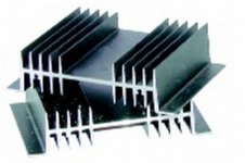

W.=100mm,L.=100mm,H.=50mm, Wt=0.49g, Rth=1.1degC/W
It is nice quality (serated fins)

Heatsink,W.=200mm,L.=100mm,H.=25mm,Wt=0.55g,Rth=0.9degC/W

L507511-01.gif,PI,1654,671, Heatsink,W.=100mm,L.=150mm,H.=40mm,Wt=0.746g,Rth=0.86degC/W
Greg, I have a sink like that I plan to use on a low power chip sub...
Yes Greg..those ones...watt values will depend the dimensions and fins numbers
Nordic.
The second one had length strange to me...as length normally is the bigger dimension...well...i have evaluated using the length you informed.
Of course things turns very different with other dimensions.
The idea is to dismount the heatsink...having in that second sittuation, 29 plates of aluminium (fins) and the base.....calculating base area, it will be added to the 29 plates area....result will enter calculation of a proportion...a ratio...using 100 square centimeters beeing 10 watts rms amplifier (140 heat transfer)
This is not precise...eye evaluation...fast and simple calculations..dismounting and evaluating...having a reference.
regards,
Carlos
Attachments
All those heatsinks look like Fischer heatsinks.
Edit: could be aavid thermalloy too.
1st sk88, 2nd sk42, 3rd sk120.
Thermal resistance is similar for all three, so i'd choose the one which is most convenient.
The one i use is sk85, has a thicker base (better for spreading heat) , base = 10mm.
I'd use one per channel, i think Carlos' calculations are too optimistic. Even with one per channel, i'd use the thermal compensation.
Example: if you are aiming for a maximum heatsink-temp 20 degrees bove ambient, a 1degree/watt heatsink can only dissipate 20 watts.
In reality it's even worse, because most manufacturers state their figures at a heatsink-temp of 80 degrees celcius.
Hope this helps,
Klaas
Well...optimistic or not, they are working fine those last 35 years
And practical world thing is what interests me.... if working, correctly rated or underrated do not bother me...if C/W is rigth, if is above 10 degrêes of environment or 20 degrees...not burning my transistors i feel good with them.
I started to do tests about 1971... since them i am using those strange numbers as reference to me.
Those early days we had not all informs needed...so..we had to discover the adequated size to the power you will have in your amplifier.... informations were obtained just observing what factories were doing about...and tests could confirm some reference numbers you could create, or discover, to reference your work.
Of course not precise...i do not want to compete with those calculations made to modern heatsinks... just i prefer my old and easy way.... and it is prefered because easy, i know how to make it...and the other complicated calculations i do not know... also, i am living those years without the need of this knowledge.
Also...my finger sensors understand, and my brain ligth the red emergency ligth related "Heat!" when heatsink temperature rises above 50 degrées celsius.... interesting that computer chips also are keept under that temperature too.
Nordic
All your heatsinks will work fine with a single channel...i think you have one that is able to hold 100 watts...this one may hold two channels at normal listening levels...of course..continuous tone is another sittuation....not music... steady tones are used for test signal purposes normally.
Those sizes, obtained during practical work, were checked with amplifiers constructed...many heatsinks were tested....and since they were not burning transistors...reaching some stable temperature that will not raise more than that one.... good!...I think.
To my place... 29 degrees average... they work fine...but of course, receiving heat, they turn hot.....not infinite heatsinks they are...just heatsinks.
Here is another sketch...showing the tricks i use.... area exposed to air is only one side... 10 centimeters side aluminium...square aluminium, will hold amplifiers working without steady tones...playing musical signals....non heavily distorted, 10 watts will be happy with that aluminium...of course, it needs the adequated convection position to cooling.
Please, do not add both side areas during calculations....of course both sides will work...but for calculation purposes, each fin need to have its length multiplied by its width... acumulate all fins together and add with base area...them... each 100 squared centimeters obtained will be enougth to a 10 watts non distorting audio amplifier.... and so on... 2 aluminum plates with that dimension will be enougth to a 20 watts amplifiers..easy calculations i am trying to provide... as worked for me those years.
regards,
Carlos
Attachments
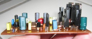
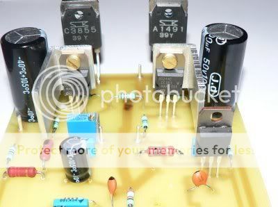
Dx amplifier transfers heat to all kind of heatsinks
A very flexible amplifier....will match your taste.... will be good to your needs.
"Construct it vertical or horizontal, Dx amplifier is sensational"
"Never fear...Dx amplifier is here"
Image is a non working model...just to be shown..values you can read are not the correct ones you may find in the schematic.
regards,
Carlos
Attachments
I must have mis-interpreted your calculations, Carlos.
I thought when you stated dissipation you meant inernal dissipation in output-stage.
For practical use your rule of thumb looks correct to me for class-ab amplifiers.
My soldering-iron died on me today , made some heatsinks for the drivers:
With kind regards,
Klaas
I thought when you stated dissipation you meant inernal dissipation in output-stage.
For practical use your rule of thumb looks correct to me for class-ab amplifiers.
My soldering-iron died on me today
, made some heatsinks for the drivers:
With kind regards,
Klaas
- Status
- Not open for further replies.
- Home
- Amplifiers
- Solid State
- Destroyer x Amplifier...Dx amp...my amplifier