Respecting if PNP or NPN, respecting the voltage limits of your transistor, the
current that they will operate.... selecting if they are Radio Frequency (do not use) or audio frequency the amplifier will operate.
It will operate with fakes, fauses, Junk parts, mismatched transistors will produce some off set to adjust.
This amplifier loves used (and already tested) parts.... have enormous passion by old greasy dirty condenser (you can clean them)
And feel very good if the construction is ugly...it will sound pretty even this way.
And will smash some amplifiers you may compare.... and will be almost so good as the better ones.
Good experience to destroy many myths.
Sorry to remember...shorted transistors will not work...but Germanium ones may operate if you take care with bias....One Germanium to the VAS will produce an incredible nice sounding...try it!...ahahahahah
regards,
Carlos
Those fake ones normally are lower power transistors..so... using it, it is better
...to install rail fuses and output fuse...at least to protect speakers if someone, underrated for the need, burn.
It is hard to know the ones are fake and the ones are not...it is confused, as some fakes are much better in details and quality..outside look, than the real ones.
Real ones...those Toshibas, are so awfull that you may think they are fake...it is hard to read the numbers on them
It is more probable to obtain good ones and imagine that they are fakes than the opposite.
Maybe this is the key...search for awfull ones...they may be good.
bye Sparkle
Carlos
The amplifier was simulated too..you can see it in full throotle
I made all i know about simulations.... Lineup will finish that simulation as he is good to use those programs.
Please line up..do it for us!
The stereo version is wainting....maybe i will remove some by pass capacitors, feedback capacitor or introduce bigger condensers somewhere..... testing is beeing done all day long... searching for audible increases.
regards,
Carlos
Attachments
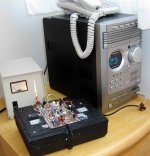
I am using my System's headphone output as my signal source
The headphone output is the only analogic audio i have there...and this output is very good...made with a good Phillips chip amplifier, dedicated to headphones....and there are many volts there...audio volts.
Impedance there is 32 ohms...reason why i am using an attenuator in my own circuit.... customized to my personal needs...this is not shown in the schematic provided.
regards,
Carlos
Attachments
Mr Greg Erskine offered schematic, layout and parts list for us
Thank you very much Greg.... pretty work.
ATTENTION....my error...not Greg error...the VR1 trimpot is 10K..and it will be adjusted to 6362 ohms.
Also intall 1K resistance to both differential colectors..will work sligthly better than 820 ohms.
regards,
Carlos
Thank you very much Greg.... pretty work.
ATTENTION....my error...not Greg error...the VR1 trimpot is 10K..and it will be adjusted to 6362 ohms.
Also intall 1K resistance to both differential colectors..will work sligthly better than 820 ohms.
regards,
Carlos
Attachments
destroyer X said:...to install rail fuses and output fuse...at least to protect speakers if someone, underrated for the need, burn.
It is hard to know the ones are fake and the ones are not...it is confused, as some fakes are much better in details and quality..outside look, than the real ones.
Real ones...those Toshibas, are so awfull that you may think they are fake...it is hard to read the numbers on them
It is more probable to obtain good ones and imagine that they are fakes than the opposite.
Maybe this is the key...search for awfull ones...they may be good.
bye Sparkle
Carlos
whoaaa....you are quick.....as someone told - to fast for us my friend.....you should call yourself "Turbo Carlos" not "Destroyer X"....the problem with fakes is not only smaller power that they can withstand but also some change related internal capacitances and this may produce some problems related stability.....that is why i have asked you to tell me if it will be stable with fakes and if i have to chenge some parts in sch if i use fakes....(i believe that in GEM guys have to change some values otherwise the stability of the amplifier is in question - i wonder if this is here the same thing - it seems it is not and that is good)
BTW.... nice schematic.....
Here is the parts list...bom as Greg said.
DX The amplifier - Bill of Materials
Date last updated: 14 February 2007
Table of contents
Semiconductors 1-1
Capacitors 1-1
Resistors 1-2
Miscellaneous 1-2
Semiconductors
Qty Value Notes
Q1, Q2 2 2N5401 PNP Input differential pair
Alternatives: BC556, BF423, BC556 and BC640*
Q3 1 TIP41 NPN Voltage amplification stage (VAS)
Alternatives: BD139
Q4 1 TIP41 NPN Driver
Alternatives: BD139, MJ340, TIP31
Q5 1 TIP42 PNP Driver
Alternatives: BD140, MJ350, TIP32
Q6 1 2SC5200 NPN Output
Q7 1 2SA1943 PNP Output
Z1 1 1N4742 12V Zener diode – 200mW or more
Capacitors
Qty Value Notes
C1 1 4u7F MKT Polyester
C2, C4, C7, C8, C11, C13, C15, C17, C18 9 100nF MKT Polyester
C3, C6, C12 3 47uF/50V Electrolytic
C5 1 220pF NPO Ceramic
C9 1 12pF NPO Ceramic / Silver Mica
C10 1 220uF/16V Electrolytic
C14 1 5p6F NPO Ceramic / Silver Mica
C16, C19 2 1,000uF/50V Electrolytic
Resistors
Qty Value Notes
R1 Not used
R2, R6, R10 3 2k2
R3, R11 2 39k
R4, R8 2 100
R5 1 1k
R7 1 4k7
R9 1 1K
R12 1 2k2 1 watt
R13 1 2k7 1 watt
R14 1 330
R15, R18 2 82
R16, R17 2 33
R19 1 120
R20, R21 2 4R7
R22 1 10 1 watt
R23 1 10
VR1 1 10K
VR2 1 100
Note: All resistors are standard metal film 250mW except were noted.
Miscellaneous
Qty Value Notes
L1 1 27 turns of 0.6mm enamelled copper wire is wound around R23 forming the output coil.
Those fakes tends to oscilate...so..you will use stop resistors and install
33 to 68 picofarads from Colector to Base...it may block oscilations...if continue....well....remove those fake ones.
Thank you..i am making some effort to provide all informations possible.
I will have to write the circuit description and inform the board size too.
regards,
Carlos
33 to 68 picofarads from Colector to Base...it may block oscilations...if continue....well....remove those fake ones.
Thank you..i am making some effort to provide all informations possible.
I will have to write the circuit description and inform the board size too.
regards,
Carlos
") please
please All rigth sparkle...i will do it soon
I am doing fast because i have friends cooperating...you have made the first schematic...i have Greg Erskine cooperating...Hugh Dean is sending suggestions and evaluating the schematic, pointing errors...also Graham Maynard is helping all time long....Mr John Mateus use to help me too.... also Lineup is supporting me.
Well... with those guys things goes running faster and better...the problem is when i do not do things they suggest...the result will be errors that will soon be discovered...they must exist..this is normal to happen...every amplifier have something not so well made that has room to be tweaked, arranged, upgraded or updated.
regards,
Carlos
Here is what i think about this amplifier.
My advertising...my propaganda.
.....................................................
Dx Amplifier
This amplifier join the simplicity of a bootstrapp
design with long time listening tests.
It is able to reproduce clear treble and deep bass
treble reproduction has not the common harsh
you may find in many industrial amplifiers.
The bootstrap operation, already push it to high
level of sonic quality.
You will feel the romance of its sound and will
dive into a nice ambience because of deep focus
off sound resolution.
The transient reproduction is fair, within the limits
of the good ones, the bass is a punch in you chin,
and will shake your leg’s hairs.
you will be you worried about your speaker
survival. Voice coil goes almost out of the limits,
out of the speaker chassis extructure, bass power
strong and decided…audio transference to speaker
is great, your speaker coil may lift from the magnetic
piece as happened with my woofer.
I want to say that this amplifier is not so good as
Others…it is better, because Ximple, because
Xcheap, having Xtraordinary sound and easy off
Construction.
Also you will not tune broadcasting stations with
This unit, .for sure!
Carlos...Destroyer X
Here is the black and white image...the black dots at your rigth
Are made to install big electrolitic condensers for rails...i was not sure and i have asked Greg Erskine to let them optional...this way..the ones will use it can use wires to connect them into the supply input..others can cut them out or keep them just as decoration pieces.
Watch the colour diagram and you will see lines..they are for electrolitic condenser connections into the circuit...optional.
regards,
Carlos
Attachments
- Status
- Not open for further replies.
- Home
- Amplifiers
- Solid State
- Destroyer x Amplifier...Dx amp...my amplifier