short
Hi Carlos, i was to fast and incomplete..
You said:
Watch the colour diagram and you will see lines..they are for electrolitic condenser connections into the circuit...optional.
If i follow the plus wire for cap C16 it is wired to the V+ and downwards via C15, +C18 to the groundconnection on the groundtrack in post 39.
Maybe i need new glasses...
Loek
edit: rotate C16 and connect the wire to the tophole and V+ is my idea
I am not different...i use to produce much more errors in a day than others do in a
week..... i am really needing new glasses..i am 55 years old Loek.
No problem...welcome to the Club man...and enjoy.
You know Loek...i have a problem with our forum...i do not know the country by the flag...and some people do not inform...and i turn confused... curiosity.... i want to know and i do not know how.
Maybe Google will provide me some International flags.
regards,
Carlos

flag
Carlos, then you are young compared to me........
And if you are interested in ice skating you could know it is the DUTCH flag....because we have a new worldrecord for the 5km track since last sunday!
On my job was a Brasilian student and allways his roomdoor has a Brasilian flag when there are international football games ....
But there are more countries with the same RED-WHITE-BLUE colours, and therefore is maybe as difficult as to read the colorcode on those small components.
Have good time with DIY,
Loek
edit:you are fast as always...
Re: I am not different...i use to produce much more errors in a day than others do in
right-click on any flag ,then click on "properties" will give ya more than enough info
")
destroyer X said:week..... i am really needing new glasses..i am 55 years old Loek.
No problem...welcome to the Club man...and enjoy.
You know Loek...i have a problem with our forum...i do not know the country by the flag...and some people do not inform...and i turn confused... curiosity.... i want to know and i do not know how.
Maybe Google will provide me some International flags.
regards,
Carlos
right-click on any flag ,then click on "properties" will give ya more than enough info
Oh!...great information...and so simple...all rigth
i have made the rigth click...your place is Serbia....Sérvia in my language.
Do not tell people...hehe..our secret...this shows me that moderators do not read my texts (maybe because awfull and wrong)...hehe...more freedom to me.
Now i will use more sheet...say...sheets of paper in my electronics work.
they did not came to instruct me that obvious feature..the old and good rigth click.... this is the way to discover things..they are not monitoring me...hehe...gooooood!
regards,
Carlos
The amplifier continues to run fine..i was checking if some bias variates and nothing
happened as i hope.
Also i checked the current in both long tails and they do not move...as expected too.
I was trying to burn one Black gate...that burn in process.... that changes the sonics....hummmm...negative...maybe i will have to burn it with soldering iron, for sure damaged they will sound clearly different.
I know.. many good guys confirm Black Gate qualities....i do not know...maybe my speaker...it is strange to me...maybe sutís...subtile differences may exist...maybe to waveform monitors or spectrum analisers.... how knows, distortion meters.
I think those instruments turns very happy when they listened those better sounds.
regards,
Carlos

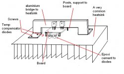
Board size is 95 by 60 milimeters
You can install output transistor over the board, in the standard traditional position....you can try them under the board twisting the leads, you can run wires from the board to the heatsink and also you can produce some kind of "bridge" blade of aluminium that will cross the board in the width direction, having 90 angles down the legs to be attached to heatsink.
Also you can remove those condensers (they do not sound with a good supply and using low speed transistors as VAS and drivers) and use an "L" shape aluminium blade to attach in a heatsink alike Aksa.
Well, depends your imagination.
My supply, i think it is good enougth...having snubbers and big condenser...near to 15000 each rail...it is using coils in series with positive rail..also in the negative rail.... 6800 uf before the coil and another 6800uf after the rail (each rail)...it is discharging after 15 seconds after the shut down of the mains supply...low volume without bass of course.
Attached the most complicated option...let your creativity free boys!
This one has not "That" good heat transference...even using heat compound...the contact area is not so good.
regards,
Carlos
Attachments
destroyer X said:wonderfull girl...an Anjo!
Carlos,
i'm living with one, she even has the name. (without feathers)
Please don't click on my properties, my real one is a roll of toiletpaper. The one and only sheet i use.
You like to carry a handbag amplifier when you go shopping ?
hi
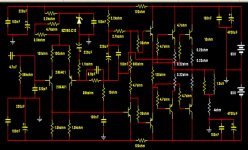
This is current version Dx-Amp schematic
http://www.diyaudio.com/forums/attachment.php?s=&postid=1134970&stamp=1171455661
Is there anything me would change, if I build this amplifier?
No, not much.
It is basically a good amplifier.
I have no doubt it will work good, in this Original Version!
A few details I possibly would try to tweak, to see if they would improve anything.
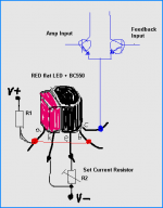
1. Use constant current source instead of ZENER in input.
I avoid as much as I can to use ZENER Diodes in my amplifiers.
There are very good alternatives.
( See my attchment )
2. Use a transistor VBE Multiplier, instead of R14 + VR2.
I like precision and good control of bias.
3. I would like to use BD139 and BD140, to replace TIP41/42.
This is because I know these better.
Good to use components that you are familiar with. Have used before.
4. I would try MJL21193 MJL21194 for output. THEY ARE GOOD!
Most because I can not buy those super 2SC5200 / 2SA1943, at my suppliers.
5. I would use 22-47pF for C14. In my version Q3 would be BD139
6. I would remove C10, 100uF and C11, 100nF
It should be possible, in this amplifier, to TRIM any DC-offset Voltage in output.
Very close to 0.00 Volt.
Regarding BIAS Offset compensation I have posted
a couple of articles in forum. Using different methods.
This is one of them:
Offset Correction using Bias Compensation
Regards, lineup
This is current version Dx-Amp schematic
http://www.diyaudio.com/forums/attachment.php?s=&postid=1134970&stamp=1171455661
Is there anything me would change, if I build this amplifier?
No, not much.
It is basically a good amplifier.
I have no doubt it will work good, in this Original Version!
A few details I possibly would try to tweak, to see if they would improve anything.
1. Use constant current source instead of ZENER in input.
I avoid as much as I can to use ZENER Diodes in my amplifiers.
There are very good alternatives.
( See my attchment )
2. Use a transistor VBE Multiplier, instead of R14 + VR2.
I like precision and good control of bias.
3. I would like to use BD139 and BD140, to replace TIP41/42.
This is because I know these better.
Good to use components that you are familiar with. Have used before.
4. I would try MJL21193 MJL21194 for output. THEY ARE GOOD!
Most because I can not buy those super 2SC5200 / 2SA1943, at my suppliers.
5. I would use 22-47pF for C14. In my version Q3 would be BD139
6. I would remove C10, 100uF and C11, 100nF
It should be possible, in this amplifier, to TRIM any DC-offset Voltage in output.
Very close to 0.00 Volt.
Regarding BIAS Offset compensation I have posted
a couple of articles in forum. Using different methods.
This is one of them:
Offset Correction using Bias Compensation
Regards, lineup
Attachments
loek said:plus C16 is short to ground....
Loek
Hi Loek,
Thanks for having a close look. It just a optical illusion.
I moved C15 a little to the left so you can see what happened. It's hard to make mistakes once the schematic is right.Carlos is thinking about leaving these caps out as he has found little or no sonic improvement with them. That's why I haven't routed them in yet. I tried to keep the layout close to the original hand made layout.
regards
Attachments
Good that people is following this thread..it is a nice amplifier, one day you will
have sure.
Jacco...yes...the sketch shows something alike a handle...hehe
Lineup...VR1 is wrong, correct is 10K...the adjustment will be bigger than 5000 ohms
R9 can be 1K
To easy off adjustment, as the total resistance there will be 413 ohms...the bias trimpot can be 100 ohm, it was 500 ohms in earlier schematics...just details...the amplifier works fine the way it is in the schematic.
Also you can use BD139 in your output simulator...it will works..simulator do not burns transistors when power is too much to them...hehehe
Thank you by the pretty CCS....sketch is good...made by my friends hands.
regards,
Carlos
lineup said:Is there anything me would change, if I build this amplifier?...
A few details I possibly would try to tweak, to see if they would improve anything.
If I was building it, in order to keep as much as possible true to the original design, but also to be able to sleep soundly
this would be my list of minimum changes:1) Replace R14 & VR2 with a Vbe multiplier (and bypass it with a small non-inductive cap)
2) Remove R9 (replace with a short)
3) Increase C3, C6 and especially C12 to 220uF.
I would also probably use BD139/140 instead of TIP41/42, like Lineup, I have used them before and I like them for rail voltages up to +-40V. I don't think i would want to change 2SC5200/2SA1943, or, if i did, it would probably be for a similar construction transistor (LAPT). I think that choice is the one enabling easy removal of emitter resistors, as LAPT constructions effectively contain a distributed 'emitter resistor' insde the transistor itself. I don't have much against zener diodes provided they are for voltages between 12 and 33V and temperature drift is not overly important - so I would probably start of without a tail CCS for the input stage. Finally, i would probably use a fixed resistor for VR1 and R7, once I figured out the adjustment.
Excelent, all sugestions are beeing observed, my group of near friends are also
evaluating those suggestions...Graham is following the thread.
He wants to discuss, but i will not publish his arguments because forum do not accept that we post third person's messages...i was punished because of that in 2004 - 2005.
Also, not talking in Graham's place, maybe he will have interest to enter, as he was not banished..he is not happy with forum freedom, as he understand this as an excess.
regards,
Carlos
DX Turbo version.... maybe will go to 300 RMS over 4 ohms
I have tried only with 8 ohms...and my speakers could not hold...it is a monster.
Sounds is sligthly better in trebles...maybe the first resistor removal..the input one.
Of course you can increase the input capacitor at your will..this is a suggestion...you guys are free to do whatever you want.
I do not like.... as i can burn my speakers...it has that idea of superiority because big power.... fooling myself because of that...the schematic is almost the same.
My supply, to that voltage is worst...really worst!
Use 2SC4793 for VAS and for the NPN driver...use heatsinks...those small ones or attach them to the main heatsink...use diodes in place of resistor in the bias control, as this animal overheat because too much power.
For the PNP driver use 2SA1837
Carefull not to miss the miller capacitor, those transistors goes to 100 Megahertz in the datasheet...but real world they go to 150 or more!
Use two pairs...maybe more if you will open all volume using 4 ohms, with a continuous tone...a steady tone or some music very constant in level..different form the standard average leveled musics.
The power Trs remains the same... 2SC5200 and 2SA1946
Enjoy boys...and be carefull..hehe...your speaker coils may melt.
Use fuses in the output and in the positive and negative rail.
Sensitivity is normal... 750 milivolts will drive it to full undistorted power.... simulator shown 318...but i did not test real world..i have not load to this range of power.
Attention to some new values of resistors...also the electrolitic condensers increased in value and in insulating voltage.
regards,
Carlos
Attachments
- Status
- Not open for further replies.
- Home
- Amplifiers
- Solid State
- Destroyer x Amplifier...Dx amp...my amplifier