Yes...it is strange to me..... because of that i felt it as fake
I may be wrong, it is not the first or second time i go wrong....my mind is always boiling, with thousand ideas into three old neuroniuns operating...so... a lot of errors happens.... but.... But they continue strange...have you tested them hard?
Have you pushed them to maximum power into Dx Standard...over 4 ohms...entering distortions?.... have they supported?
Are they included into your transistors/parts packages?.... will our friends that ordered boards use them?
Have those ones good flat back surface?.... i have never watched one of those ones into my hands, say to feel the weigth and observe some details... reason why i am so surprised with them.
regards,
Carlos
Attachments

OK, nearly had some tears.... was a little stupid when I soldered in the output transistors and swapped them around. Luckily I used the protection resistors, and it was drawing about 1.5A over them. Quicklhy powered down, and prepared to put in new transistors... decided at the last minute to test the ones I thought was now dead... and they measured fine.
Reinstalled them, the right way around this time. Powered up, dialed in about 500mA over the protection resistor. Offset only 3.4mV.
So I believe all is good.
Need a small rest now then I'll hook up a source and a speaker.
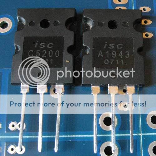
Yep I know they are not Toshiba, but they don't claim to be...which gives me more trust. Very heavy, cases are pretty flat but can do with some lapping if you want to use a hard isolator... fine for silpads.
They are not part of the kits... I only found a supply later.
Reinstalled them, the right way around this time. Powered up, dialed in about 500mA over the protection resistor. Offset only 3.4mV.
So I believe all is good.
Need a small rest now then I'll hook up a source and a speaker.
Yep I know they are not Toshiba, but they don't claim to be...which gives me more trust. Very heavy, cases are pretty flat but can do with some lapping if you want to use a hard isolator... fine for silpads.
They are not part of the kits... I only found a supply later.
Those folks can resist to more than 10 amperes.... for small time only
They do not transfer heat very fast... 10 amperes when your supply voltage reduce to 30 volts means 300 watts.... they cannot hold that...but for seconds they can.
Very good and huge transistors the Toshibas i have... also, even better, the Fairchild i have.
I never had a fake unit, well...those pairs... 2sc5200 and 2sa1943...never had problem.... also i am not a big buyer...i have only 10 pairs.
I am happy that you trust on them....good.
regards,
Carlos

Nicootje,
the ISC devices need not be bad ones.
ISC also manufactures same number "equivalents" of the Sanken 2SA1294/2SC3263 duo.
The updated version of a popular Eastern neighbor monaural power amp model carries the ISC versions instead of the original Sanken output devices.
For "better" sound reasons.
the ISC devices need not be bad ones.
ISC also manufactures same number "equivalents" of the Sanken 2SA1294/2SC3263 duo.
The updated version of a popular Eastern neighbor monaural power amp model carries the ISC versions instead of the original Sanken output devices.
For "better" sound reasons.

Seems my second channel is osscilating. Bais runs up a little fast, and output transistors are getting hot...
DC offset is good.
tried with 100pf as miller cap, will try something higher tommorrow... just too tired now.. think I'm going to be asleep by 9 o' clock tonight.
DC offset is good.
tried with 100pf as miller cap, will try something higher tommorrow... just too tired now.. think I'm going to be asleep by 9 o' clock tonight.
So there I am, sitting, looking at the two PCB's side by side...
Puzzled, how come DC offset so low, but transistors getting hot so fast... Then I had a bright idea.
Ohm meter from bias servo + to - points on good board, then duplicated the reading on the naughty board... turns out I misadjusted that one before... at least now I have good values for onnboard measurements.....
Channel seems dead happy now... ofset a whole 0.3mV
Will sleep realy well now, this would only have invaded my dreams... dreams are for beautifull girls and exotic places you never visited before...
Fried one PSU inductor... whole room was filled with smoke... and it killed the resistor connected to it... damn new probes, haven't taped them up yet, normaly I only expose the tips. Made new inductors with heavy guage oxygen free copper wire, that I got from my friend who makes the cables. So only have one working PSU up now... Good to know PSU traces are stronger than solid wire...

Still reading all about DXHRII, I think I will construct it! I am now on topic where Pr. Carlos is telling about bridging DX's. I need to burn those brother's subs! It was a thunder kick but my DX Turbo didn't melt them! +-56V PSU @ 4 ohm it is about... I don't know how many watts but it was something incredible!!! Cars trunk is damaged
I love my Turbo's!!! I am only 25 years old and I like extremely deep bass! I think I will fall in love with Dx Bomber and nothing to tell about my next wife DX HRII
Sweet dreams Nordic!
Thanks Pr. Carlos
regards, microp
Attachments

Good to read the "last adventures of nephew Nordic"
The output.... fast hot....hummmm.... those transistors...something is telling me bad things about those folks.
I do not trust them.... the worst problem is not the possibility of real fake or not real fake.... the problem, inside me, is the low confidence into those folks...so.... i will have the natural suspection on them.
Graham said fake transistors use to oscilate, into his schematic he sugggest inclusion of capacitors from base to colector when we have suspections of oscilations starting there.... i would like to know the gain of those units....normal 2SC5200 have gain from 70 to 110... this is what i have found here..... the gain is a nice indication if inside the capsule, if we have a real 2SC5200 silicon piece or not.
regards,
Carlos
.....................................................................................................
And i feel very happy that you are around dear Arnis.
Your friend's proud smile...hehe..... you will take care of this..... for sure.
Each time i look to those transistors Nordic is using... i have the fake sign blinking inside my head.
ahahahahaha.
regards,
Carlos
Attention Dx constructors, a very important message.
I am asking Greg Erskine help, because my language problems to explain what i mean.
But i will try:
The multiturns trimpot is not the better option....it is worst to daily work...it is slow in speed...you have troubles to go from maximum to minimum resistance immediatelly..... also you feel lost not knowing if counter clockwise is increase or decrease...and during a measurement, when the current is showing 10 amperes because of misadjustment, you cannot be fast enougth.
The normal, old trimpot, that one you turn with a screw driver, this one is faster...you go from maximum resistance to minimum as a flash... as a ligthning...instantaneously.
Is this really needed?
Yes, it is really needed to diyers.... we have not that enormous experience...and also we use to tweak, to change circuits, to use different voltages than the provided schematic.... off set errors and different gain into transistors will result in different resistances into your VBE multiplier "trigger" resistance... the one will make the VBE multiplier to conduct...to conduct more...or even to stop conduction.
We use to give the aproximatelly needed resistance to a pre adjustment into the trimpot...but people can measure wrong.... not adjusting to the correct tape.... also the trimpot can be installed into the PCboard using only two pins, as a variable resistance... and pins 1 and 2 will present some resistance that will be very different from 2 and 3 pins resistance..so.... depending how you install them you will have different resistances presets.
As i use the normal, old, circular movement trimpot... a circle having 270 degrees, and you can go from maximum to minimum very fast...so...detecting big current... as a flash you go to other extreme...this allow you fast correction of big errors...and, of course, alike the multiturns you can adjust it with preset values too.
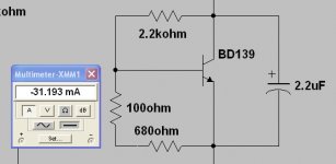
Into the High Resolution, and depending the supply voltage and the transistor gain, ...in special the VBE multiplier transistor unit gain, you will have different results....the prefered resistance to start is 700 ohms..... also 750 ohms will be good to start.
The 1K trimpot, starting adjusted to mid range (500 ohms) will be reasonable too..... but, even having a high range, it is dangerous because you can adjust a very high current to the rails.
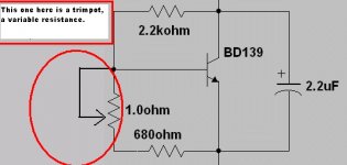
So...and because of that, i am showing an option..... the use of a fixed resistance in series with a smaller value trimpot...the adjustment will be easier this way...you will have limits too.... a fixed resistance of 680 ohms, by itself, usually, is the needed value..so... the trimpot will be at the maximum value into your starting adjustment position.... so...you will have 680 plus 100 ohms... total will be 780 ohms.
The higher the trimpot resistance the smaller will be your bias current.
You will see, watching the three images i will attach, that smaller resistance means higher current... and the trimpot limits of maximum and minimum resistance adjustment what will represent into your bias current.
I hope you could understand me...because this is very important.
Please dear Greg, go tracking to help me, the language is a problem to me.
regards,
Carlos
Th
I am asking Greg Erskine help, because my language problems to explain what i mean.
But i will try:
The multiturns trimpot is not the better option....it is worst to daily work...it is slow in speed...you have troubles to go from maximum to minimum resistance immediatelly..... also you feel lost not knowing if counter clockwise is increase or decrease...and during a measurement, when the current is showing 10 amperes because of misadjustment, you cannot be fast enougth.
The normal, old trimpot, that one you turn with a screw driver, this one is faster...you go from maximum resistance to minimum as a flash... as a ligthning...instantaneously.
Is this really needed?
Yes, it is really needed to diyers.... we have not that enormous experience...and also we use to tweak, to change circuits, to use different voltages than the provided schematic.... off set errors and different gain into transistors will result in different resistances into your VBE multiplier "trigger" resistance... the one will make the VBE multiplier to conduct...to conduct more...or even to stop conduction.
We use to give the aproximatelly needed resistance to a pre adjustment into the trimpot...but people can measure wrong.... not adjusting to the correct tape.... also the trimpot can be installed into the PCboard using only two pins, as a variable resistance... and pins 1 and 2 will present some resistance that will be very different from 2 and 3 pins resistance..so.... depending how you install them you will have different resistances presets.
As i use the normal, old, circular movement trimpot... a circle having 270 degrees, and you can go from maximum to minimum very fast...so...detecting big current... as a flash you go to other extreme...this allow you fast correction of big errors...and, of course, alike the multiturns you can adjust it with preset values too.
Into the High Resolution, and depending the supply voltage and the transistor gain, ...in special the VBE multiplier transistor unit gain, you will have different results....the prefered resistance to start is 700 ohms..... also 750 ohms will be good to start.
The 1K trimpot, starting adjusted to mid range (500 ohms) will be reasonable too..... but, even having a high range, it is dangerous because you can adjust a very high current to the rails.
So...and because of that, i am showing an option..... the use of a fixed resistance in series with a smaller value trimpot...the adjustment will be easier this way...you will have limits too.... a fixed resistance of 680 ohms, by itself, usually, is the needed value..so... the trimpot will be at the maximum value into your starting adjustment position.... so...you will have 680 plus 100 ohms... total will be 780 ohms.
The higher the trimpot resistance the smaller will be your bias current.
You will see, watching the three images i will attach, that smaller resistance means higher current... and the trimpot limits of maximum and minimum resistance adjustment what will represent into your bias current.
I hope you could understand me...because this is very important.
Please dear Greg, go tracking to help me, the language is a problem to me.
regards,
Carlos
Th
Attachments
Nordic will not be happy with me, but this modification is needed... very late, but
needed to make your life more confortable.
The original is not wrong ...but worst to adjustment.
substitute your supplied trimpot by a 100 ohms unit.
Cut one of the extreme track and insert, under the board, over the copper line, a fixed resistance...a very small one.
This way.
regards,
Carlos
needed to make your life more confortable.
The original is not wrong ...but worst to adjustment.
substitute your supplied trimpot by a 100 ohms unit.
Cut one of the extreme track and insert, under the board, over the copper line, a fixed resistance...a very small one.
This way.
regards,
Carlos
Attachments
So... a small cut into the copper line, with a small knife and you will have the
...point to insert your resistance...the one will be in series with the 100 ohms adjusting trimpot.
Observe, into this diagram, that you have a fixed resistance (680 ohms) and the other one is the variable resistance, the trimpot.
regards,
Carlos
...point to insert your resistance...the one will be in series with the 100 ohms adjusting trimpot.
Observe, into this diagram, that you have a fixed resistance (680 ohms) and the other one is the variable resistance, the trimpot.
regards,
Carlos
Attachments
It is possible....or better...it is not impossible that you will need to adjust the
under board fixed resistance (680 ohms) to a bigger or lower value.
this will depend from your circuit...this happens....not always, but happens.
If your bias result too much big, even increasing the resistance to maximum value..the trimpot resistance... than substitute the trimpot to a higher value (220 ohms)...or keep the trimpot and increase the resistance to a higher value...in our sittuation will need another one in series, because 820 ohms is too much big.
If your bias result too much small... even decreasing the trimpot resistance to minimum value, than reduce the under board resistance to 560 ohms.
I think this will not be needed...but it is good to be posted as exceptions can happens too.
regards,
Carlos
- Status
- Not open for further replies.
- Home
- Amplifiers
- Solid State
- Destroyer x Amplifier...Dx amp...my amplifier