Razorback, mi hermano, this is for you
About transistors.
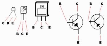
The transistors we are using into the High Resolution II are those ones... the smaller ones are BC546 and BC556.... the mid ones are BD139 and BD140...and the big guys are the output, 2SC5200 and 2SA1943.
Here you will check if you are considering the correct leads.
regards,
Carlos
About transistors.
The transistors we are using into the High Resolution II are those ones... the smaller ones are BC546 and BC556.... the mid ones are BD139 and BD140...and the big guys are the output, 2SC5200 and 2SA1943.
Here you will check if you are considering the correct leads.
regards,
Carlos
Attachments
Hermano, this is to remember you how to test transistors
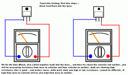
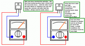
Transistors, during testing, the static DC resistance testing must understand, considerar, understood, aceitar, accept, the unit as constructed with diodes...and this is not really wrong...not absolutelly rigth and also not absolutelly wrong.
The multimeter, measuring diodes, will force a current, with a voltage bigger than 600 milivolts into the base to emitter junction... called for now on, base to emitter diode.... depending the transistor polarity, if NPN or PNP, you will have conduction or not when you fix some probe colour to testing.
The base to colector must be understood as a diode too...so..you will check both diodes..form base to emitter and from base to colector.
Result must make sense.... if you have conduction from base to emitter you will have conduction from base to colector too.
If you have NO conduction from base to emitter (high resistance measured) you may spect also NO conduction from base to colector.
This is the rule, the logics.... everything different than that will tell you that you have a defective transistor...normally they open the circuit...having high resistance during testings in both polarities or show short circuits during testings .... also you can have combination of those things.
Shorts or open circuits are defective.... and you can have base to emitter fine and base to colector shorted or opened.
Also you will need to test Colector to emitter and invert the test probes...the measurement must be high in both polarities.
The idea, during testing, is to use the diode position into your meter...and to fix one colour probe point into the base...touching the colector and emitter with the other probe....one each time..not marking shorts from base to colector, or colector to emitter.... and this will present you something that will make sense IF the transistor is good..... or will conduct from base to colector and also from base to emitter or will not conduct from base to colector and also from base to emitter...inverting the leads the sittuation have to invert referenced to the first testing.
I will show you two images.... one show the first testing, into step 1 and 2....and the other will show you step 3 , 4 and the colector to emitter, called step 5 and 6.
I hope not too much confused...the image talk by itself.
regards,
Carlos
Attachments
destroyer X said:Transistors, during testing, the static DC resistance testing must understand, considerar, understood, aceitar, accept, the unit as constructed with diodes...and this is not really wrong...not absolutelly rigth and also not absolutelly wrong.
I will show you two images.... one show the first testing, into step 1 and 2....and the other will show you step 3 , 4 and the colector to emitter, called step 5 and 6.
I hope not too much confused...the image talk by itself.
regards,
Carlos
Yes...thank you the images talk hundreds of word.....very clear and understandable...
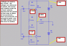
More IMAGES on how to do bias adjustment please...
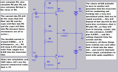
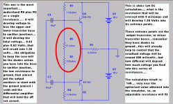
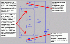
Those results are automatic or we should do some adjustment to get those resultsListening...i found the best around 590 milivolts...for those small BCs we use.... for VAS i have found 605 milivolts as nice operational point.... the second one has sligtly bigger VBE.... going to 610 milivolts.
....? Or more explaining please...
I think that the junction behaves alike a zener diode...trying to keep the voltage
stable there.... the DC bias can enter and the diode will try to keep the voltage from the base to emitter, for instance, constant, and will be around 600 milivolts (people prefer to use 650 as standard...my meters do not show this as real).
We have two things...that will result into a third thing.
The DC bias, stand by current that will cross all transistors as the first thing that normally put them to conduct...more than 500 milivolts are there (people say that 400 is enougth...my experience say different...need more than that...more than 450 milivolts)... and this forces the unit to operate, to conduct into the colector to emitter junction.... the bigger this current, the bias current, the bigger will be the condution and the bigger will be the current crossing the colector to emitter junction.... of course..if you have bigger current into the colector to emitter junction you will have smaller resistance.... transistor is correctly called this way.... Tran = transference....... sistor = resistor.... so...transfer resistance...this is a nice way to understand it.... i do not know if they have create this name thinking on that or not.
You have a second thing...the audio current.... this bias also...this drives the unit on also... even having not the DC standard bias, an audio entering a base to emitter junction will drive the transistor on... imagine audio sinusoidal.... 0.6 volts peak.... so...0.6 positive going pulses and 0.6 volts negative going pulses...depending the transistor type, the positive going pulses can put them to conduct current from colector to emitter... will have current there if you have voltage there..if not, you will have a remote (because the control enter the base...the base bias...the base to emitter current) controled resistance (the colector to emitter resistance will change.....
And you have the third things.... the effect
When you have a DC bias...the transistor conduct a small current (class AB)..... but conduct from colector to emitter.... stand by current...iddle current... when the audio enters..you will have the combinations of DC bias and the audio signal...and this will produce the third effect... the variation of colector to emitter current that will drive more or less current from the supply... this means, amplification, because into the colector you will have much more current and much more voltage (voltage multiplied by current means power) than the base bias and the base signal...so...this is called amplification.... you manipulate...control... the colector to emitter current...the supply feed you the needed energy and the the colector to emitter goes variating the resistance creating an waving voltage.... the supply voltage is variated...and theres your audio amplified signal.... combination of those signals.... now borning as a third signal..consequence of the first two ones.
The bias depends how many miliamperes you force into the base to emitter junction, and the component data sheet will show you the ratio of those currents... and this will be the gain...that will be different when you enter 1 miliampere and when you enter 100 miliamperes..so... the unit is not linear.... you have a good ratio into a limited variation of current...out of that the ratio of currents turns strange...so...we use the linear portion of that.
Forcing too much voltage, that will be current when enter the zener junction..the base to emitter junction behaves this way....you will increase the current and also the Volts base to emitter will increase...but increase very softly..... i could see, into audio that 500 to 650 are the limits...out of that audio not good...so.... you can control that bias with the resistances that feed you the current to the base... it is adjustable...you can control..but also you have that "automatic control you said"..because of zener behavior..... there are limits..you can increase the current..or voltage to a extreme point.... when passed some limit the base to emitter junction will burn, will melt, and you will have a short there, a defective and no more operational transistor...the base to emitter voltage and current has limits...so..the base to emitter power (current multiplied by voltage) will have a limit or power..... limit of voltage and limit of current.
I am not good with theories.... i am a burning fingers guys that learned that burning transistors.... long time doing that ...more than 30 thousand hours burning fingers during 46 years of practice..... but i am a little bit weak into the theories... something may be not very precise.... and we have the better guys to complete, correct or explain missed parts.
regards,
Carlos
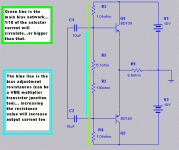
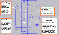
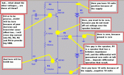
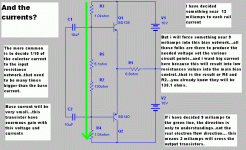
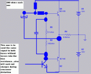
I have made some images, dedicated to Triast and to Razorback
I have made some images, to explain how the biasing happens, the need, and how to make and decide currents, voltages and those things.
It is not precise, not entirelly correct...the direction of current flows are to be easy of understanding but will not correspond, exactly, to the real thing..also will not confuse your mind and burn your neuroniuns too....relax.
I hope i can be helpfull for someone.
Enginneers..go away..this is not for you... the minimum to you is to feel bothered, offended how primary the explanation was made, so unprecise and so anti academic this can be..but works.. i have amplifiers working using this small knowledge i have.
The idea is that the study of the images, and reading the informs, will make you realise, conclude, deduce and understand how things operate.
regards,
Carlos
Attachments
Hi Carlos,
Your meter illustrations and little block diagrams remind me of the old Heathkit instruction manuals - the sort of thing which helped so many beginners, but which we hard see any more.
What an excellent DIY project this is turning out to be !
Cheers ........... Graham.
Your meter illustrations and little block diagrams remind me of the old Heathkit instruction manuals - the sort of thing which helped so many beginners, but which we hard see any more.
What an excellent DIY project this is turning out to be !
Cheers ........... Graham.
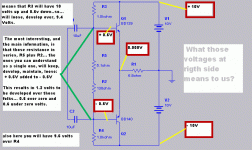
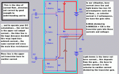
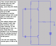
The circuit will work as a current amplifier.
Because this stage has not voltage gain... all the voltage able to be produced into the output... something alike half the rail voltage in RMS volts must enter the stage...the stage will produce current gain...the hability, capacity to develop the full voltage over low resistances, low impedances, speakers or.... something that will "suck" current in big quantity...billions of electrons will flow in small part of a microsecond.
To low impedances, alike speakers, you need not only voltage..because voltage without current will go to zero when facing low resistances..you will need power..that means the presence the voltage together with high current capabilities, capacities... able to give to the load high current and voltage.
regards,
Carlos
Attachments
- Status
- Not open for further replies.
- Home
- Amplifiers
- Solid State
- Destroyer x Amplifier...Dx amp...my amplifier