no, i have built those speakers by myself. The active crossover is designed using LEAP software and using the frequency response curves of each driver, so in simulation the response looks fine to me. the crossover is 24db/oct in all sections so the magnesium cone problems are not in the useful range. the cross frequencies are 300 and 3khz.
below is the real measured frequency response of the crossover.
The encloser also?
See link from Ed Collier
https://picasaweb.google.com/110391320683267874393/Pacific
meanman1964 how did you make your enclosures? the woofers are 8inch? this is epoxy resign or polyester with fibreglass cloth? and how thick is the wall of the woofer cabin?
http://www.diyaudio.com/forums/multi-way/189710-my-new-diy-speakers-project.html
http://www.diyaudio.com/forums/multi-way/189710-my-new-diy-speakers-project.html
Last edited:
meanman1964 how did you make your enclosures? the woofers are 8inch? this is epoxy resign or polyester with fibreglass cloth? and how thick is the wall of the woofer cabin?
http://www.diyaudio.com/forums/multi-way/189710-my-new-diy-speakers-project.html
Not my build but from a friend his brother in law whom has a company building things in fibreglass
because those heatsinks , especially at the middle top, with the amp at idle are hot enough (after about 15-20min) so you cannot keep you finger on it , they have about 68C measured (room temp 26) , should i use a fan on the heatsink? Of course when i listen music loud enough the temp rises little more. I am sure that it will lower the temp but is it necessary ? the heatsink temp coefficient is 0.19c/w for 3channels and each channel needs at least 0.5c/w. Of course these 3 channels will never be used at maximum power because i will use them in 3way active system.
Will i earn something by using fans?
Will i earn something by using fans?
Will i earn something by using fans?
$250 of electrolytic caps every 5 years.
Hi ioannidis,
I agree completely with jacco. Those amps are running far too hot.
How did you determine what to run the bias current at, and did you take the voltage into account? I don't know of any designer who would be happy things are too hot to touch and hold a finger on, that just nuts!
-Chris
I agree completely with jacco. Those amps are running far too hot.
How did you determine what to run the bias current at, and did you take the voltage into account? I don't know of any designer who would be happy things are too hot to touch and hold a finger on, that just nuts!
-Chris
i just measured the wattage drawn by the amplifier when is on idle or playing music low. it is 300w. I expected this number because i was running for several years two channel version of this amp and it was about 100w idle.
the heatsinks are hot and you barely can touch them.The idle current is about 90-100ma per mosfet and there are 24 on each heatsink.
In proportion ,you seem to have 1 -1/2 X the heatsink I have and 2.4X the
semi. Just guessing on your 100ma+ bias , just 7 pair (14 devices) would
get you 40+ C from end to end.
With just 10 devices on a 3U X12" , I get 45C (in the middle) , 38C
at the ends. I even JUST redesigned the slew output stage for Vfet's and
to spread the 5 pairs across 250mm because of just this shortcoming.
As DIY'ers , sometimes we don't get it right (first time). Your only option would
be to make single pair amps for the mid/tweeters to get the output count down.
Looking at your heatsinks , just one (section) of them is like my heatsink USA extrusion.
Just a 3 pair (MT-200)output stage on this is a perfect 40C from end to end.
So , one of your amps on one section (of one side). The remaining empty section
with 2 smaller amps. Seems to be your only option to get down to 6-7pairs
- short of a forced air setup or much larger 6-7U extrusions.
OS
Last edited:
the heatsink is 16cm (4U)x40cmx4cm on each side. i tried a 14cm low noise fan on each side at the centre on each heatsink and it seems to work fine. the heatsinks are much cooler. you can hold your hand on it very easy. they must be around 40c.
I think with those fans (you can't hear them ) it will be ok.
when i have it without the fan the heatsinks are hot as i said before but you can normally touch the output devices (irfp240/9240). they aren't really that hot. the heatsink is very hot because they are 24 mosfets on each heatsink. if i 'll use only one pair of mosfets on 4 channels will it be acceptable for the active system? If i lower the power to 50w from 200w will it perform the same in comparison for the low frequencies channel in the active system or if i turn up the volume the bass will be much louder in comparison to the mids/highs?
of course another option is to lower the bias for example at 50ma (the designer suggests at 100ma) so the dissipated power will be 50% less, but this is not a good solution isn't it?
Last edited:
yes i have but with the passive crossover. without it the impedance curves are :
woofer : E0026-08S W26FX001
mid: E0043-06S M15CH002
high: E0040-06 T29CF002
woofer : E0026-08S W26FX001
mid: E0043-06S M15CH002
high: E0040-06 T29CF002
if i 'll use only one pair of mosfets on 4 channels will it be acceptable for the active system?
Should be , look up the typical power distribution in a 3-way.
On a subwoofer'ed 2-way setup, I have observed @ 70% power going to
<100hz content. Of course , this changes with the type of music.
On the amp side of things , Mid and HF drivers don't have the "psychotic"
impedance variations that the bass does , amp works harder.
Your type system has many pluses , one can customize the amp to the driver.
For example , an overcompensated/ high current /over-designed bass amp.
Mid and high can even be a BJT CFA creation , fine tuned to the job. A very
fast settling servo with a hair trigger DC detection circuit would also be advised.
A smaller amp with just a pair of MT-200 OP's (70V rails), would push any
tweeter or midrange to VC burnout !
OS
woofer : mid: high:
4 pairs of output devices do a total Pd of 1200W : 6 times the continuous power in 8 ohm.
Looking at the data, even a 3-pair output stage could handle the woofer.
That's not even counting in that the woofer amp channel is cooling down part of the time in an active setup.
You could easily get away with less power devices for the mid/high sections.
4 (high) + 6 (mid) + 8 (woofer) would reduce the total number of devices by 25 percent.
At the same 100mA bias level, 1/4th less idle dissipation.
Hello
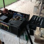
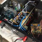
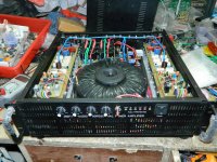
greetings my CLASS D amp with input limiter and last 2 pictures my
HD CLASS amplifier with torridal transformer wound and made at home
warm regards
Andrew
greetings my CLASS D amp with input limiter and last 2 pictures my
HD CLASS amplifier with torridal transformer wound and made at home
warm regards
Andrew
Attachments

Hello
greetings my CLASS D amp with input limiter and last 2 pictures my
HD CLASS amplifier with torridal transformer wound and made at home
warm regards
Andrew
You mean Class H ? Class D can do that (1KW) with just 2 pair to-264 MOSFETS.
For class H that is as nice as any OEM - excellent work ... very Neat !
My apologies - first one looks "D" . second amp is a "work of art".
OS
Last edited:
Hello Ostripper
greetings first picture is a class d amp for 1 ohm impedance loads
yes second amp EEE engine yamaha HD class is a sweet sounding amp
can you help me with a SSR relay 50 ampere i need to build for short
circuit protection for my amplifiers your protection circuits are state of
art i am trying simple short circuit protection with a mosfet relay
reaction time is much faster
warm regards
Andrew
Solid State Loudspeaker Relay
This looks like what i need maybe i can make it with my limited knowledge
This looks like what i need maybe i can make it with my limited knowledge
That one is close to the one I am listening to right now (21'st century protection).Solid State Loudspeaker Relay
This looks like what i need maybe i can make it with my limited knowledge
Jwilhelm updated the original mechanical. We use Infineon FET's with >100A peak.
Works real well !!
If you built those two amps - the SS relay will be easy !
OS
https://www.facebook.com/sameer.audio
Hello Ostripper
greetings the first vedio on this link is the short circuit protection copied
from QSC PL380 its working still needs to be tweaked and the SSrelay
to be used hope i can make it
warm regards
Andrew
Hello Ostripper
greetings the first vedio on this link is the short circuit protection copied
from QSC PL380 its working still needs to be tweaked and the SSrelay
to be used hope i can make it
warm regards
Andrew
- Home
- Amplifiers
- Solid State
- Post your Solid State pics here