Hi Ian
Thanks for your help
Yes I tend not to bother building something if I have to struggle to find parts
AS a Beginner I don’t yet have the Knowledge to pick substute Devices to match the ones in parts lists I have to stick with the original parts so if there’s a problem I won’t build the cct
Thanks for your help
Yes I tend not to bother building something if I have to struggle to find parts
AS a Beginner I don’t yet have the Knowledge to pick substute Devices to match the ones in parts lists I have to stick with the original parts so if there’s a problem I won’t build the cct
Probably very good if implemented correctly.
It may be possible that a higher current capability may increase performance but that depends on the loads you hang on the buffer output.
A follower integrated into the buffer output could provide that enhanced current capability.
It may be possible that a higher current capability may increase performance but that depends on the loads you hang on the buffer output.
A follower integrated into the buffer output could provide that enhanced current capability.
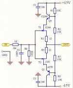
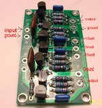
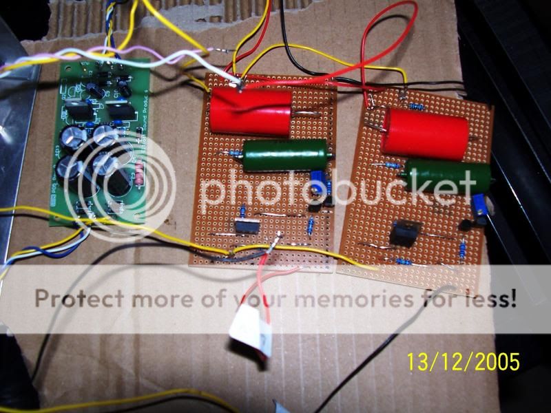
This is the buffer I use in my Dacs at the moment sounds very good I would like the views of the other mender in what they think of the cct
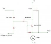
The cascode helps the J-fet linearity greatly by maintaining a constant Vds. The linearity can be further improved by also maintaining a rather constant Id as well. This allows you to set the bias wherever you wish, particularly being able to set the Q-point much closer to Idss, resulting in a lower noise figure for the J-fet. In the drawing below, the AC load of the J-fet is only the base current of the BJT, Iout/Beta(AC). This means you can use an input J-fet that has a smaller transconductance. The circuit is not particular on components, you can use whatever you have that fits. There are some J-fets that have a nice linear transfer within a certain operating area but they may operate with much less Gm, but this is OK here. The BJT and input J-fet is cascode by a high Gm J-fet (simple
)and the CCS is a medium Gm J-fet bias at Idss. (also simple). J-fets can always be paralleled for more Gm. In the drawing, the DC servo input can be set with a fixed resistor voltage divider to provide 0VDC output. The gate of the cascode J-fet can be attached to the input J-fet gate as well, but also adding the Ciss of the larger J-fet to the input capacitance. But this is of little issue since the input capacitance is bootstrapped. Having a high input Z allows the use of a smaller input capacitor, which makes more dielectric materials available such as polypropylene film.Attachments
Last edited:
You have the question back to front.Folks:
Can someone explain how you determine the correct attenuator impedence for a preamp of buffer? I'm building a Pedja Rogic jfet buffer and need to select an attenuator.........................
The Buffer allows the Attenuator to drive the cable connecting it to the Receiver.
The attenuator impedance is mostly determined by the Source.
What load can the Source drive in combination with the cable between them?
Most Sources will drive 10k, if the cables are not too long.
Some prefer to use attenuators from 20k to 500k. That is mostly down to preference, but in a few rare situations very high attenuator impedance is required by the Source.
Summarising:
The Source determines the load impedance.
The Buffer drives the cable.
[Thanks for your input CBS240
I have also built the Pedja Rogic jfet buffer but modified the schematic to suite my tube amp and it also works well with my old pioneer SA 500A and SA2600 amps
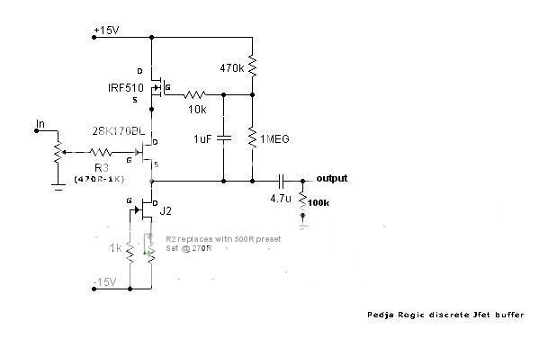
I have also came across this version of Pedja Rogic jfet buffer using the 6922 tube not sure about it thou any views on the schematic as I may try it out later
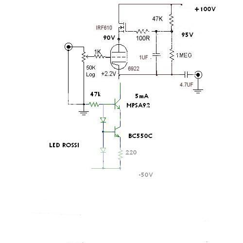
I have also built the Pedja Rogic jfet buffer but modified the schematic to suite my tube amp and it also works well with my old pioneer SA 500A and SA2600 amps


I have also came across this version of Pedja Rogic jfet buffer using the 6922 tube not sure about it thou any views on the schematic as I may try it out later

- Status
- This old topic is closed. If you want to reopen this topic, contact a moderator using the "Report Post" button.
- Home
- Amplifiers
- Solid State
- Pedja Rogic's J-fet buffer for dummies.