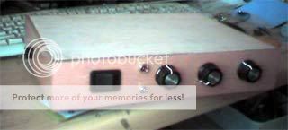
The face is another pseodo veneer, to match my amp... Ran out of varnish, so the top is untreateated... will replace that with something nicer later on.. actualy toying with screwing this to the bottom of the amp now... the sides are made of long offcuts I cut in shorter pieces and glued side by side to make planks...The balck thingy on the side is a fuse holder... pretty nice wood, offcuts from some furniture place, someone came to dump here by me...The power switch matches the one on the amp. The knobs where all I could get at a reasonable price...
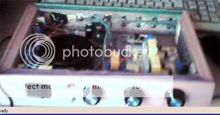
Can't see much with my camera... the gray wires in the middle is just connected to the toggle switch as a video source selector for useing the playstation... The transformer is an Avel lindberg I bought on a market, Powersupply, very basic... busy makeing PCBs for Pedja's discreet regulator to replace that now
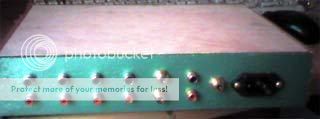
The back is from chipboard... all I could find...used hamertone spray... looks kinda nice in real life...
Nice pics of the amp here...
http://www.diyaudio.com/forums/showthread.php?postid=1087868#post1087868
Nordic said:Thanks Steve... that worked 100%
Wow these sound good... shame about the crappy PSU.... totaly went minimalistic getting the other buffer to stop oscillateing...
Its like super stereo.... listeing to some CDs now, and its pretty freaky how diffirent they sound... lots of hidden detail comming out...
Brilliant!
Incredible bass, crystal treble... very atmospheric... its like a sound effect generator... its like some of the sounds are just apearing in the room... no way my speakers can make em")
Hi Nordic,
that sounds very promising, I was going to build an OPAmp buffer for my my_ref, but now I guess I'll have to try that JFET-Buffer instead.
What do you think about this PSU for the JFET-Buffer?
thanks!
LC
lovechild said:
Hi Nordic,
that sounds very promising.
I was going to build an OPAmp buffer for my my_ref,
but now I guess I'll have to try that JFET-Buffer instead.
What do you think about this PSU for the JFET-Buffer?
LC
Pedja Rogic's FET buffer is good enough!
with coupling capacitors .....
----------------------------------------------------------------
My own idea is extremely good, too
... a follower J-fet buffer totally without any caps!
This is the differance.
Vive la difference!
My little easy circuit has features:
- No feedback
- True DC coupling
- Near to infinite speed
- Class A .. with 2 JFET adjustable constant current sources
... You want more
... I am sure you wont need more====================================
For schematic, full details and test figures:
- See my Post #11 above
- Link: http://www.diyaudio.com/forums/showthread.php?postid=1118808#post1118808
Regards
Lineup Audio Lab & Bright Ideas
lineup
at
http://lineup.awardspace.com
Guten Tag, the circuit seems to have good noise rejection for the PSU, as I made a very cheap and nasty psu (appart from the transformer), with the plan to upgrade it later, but it sounds so good, I can't get myself to open the box
Your PSU looks OK, but I will admit not likeing the fixed voltage regs, because of their higher noise level...you probably won't even notice though, I think I took mine up to about 17.5V for extra headroom.
the real trick is the frequency limiting of the buffer, those LM chips don't like wideband input... go try....
I have an eagle PCB layout, if you want to etch boards, just let me know... I have prepared the pcbs but have been too busy to stuff the parts on, layout is smaller, but wireing is more complex for pcb.
The PSU I plan to use shortly was recommended by T in post 17, and also designed by Pedja, I have untested PCB for that too, but I can't see why it should be a problem...just ask if you want
current psu is 2200u then 10r 1W in series, followed by annother 2200u, and I think .1u followed by lm317/337 and .1||100u after.
PS Lineup's ideas are also normally pretty good
How ya doing mate?
PSS
Don't waste time on that opamp circuit, I tested valves, chips and fets.... there is no competition... although I wil admit the valves were only used in straight cathode follower fashion.
Had some fun tonight upgradeing my PR buffer...
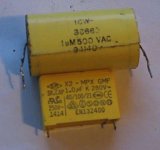
Got rid of some crappy MKP caps and replaced with relatively much better caps from ICW... then I remembered that Pedja said he had to limit the frequency in the design, to get the chipamps to work nicely with it...... so out came the screwdriver, and out went the 0u047 caps...
Was sounding a bit bright at first, but is amazeingly even more detailed than before...
Unfortunatelty I had the wife hovering in the background to watch TV, so I could not do much comparisons bewteen just the replacement of the cap, and the removal of the other cap... but watch this spot...
For gainclones.. leave the design as illustrated in the 2 veroboard drawings, This mod is only for SS and valve based systems.
Attachments

peranders said:The server is down...
Not only that but other servers located in US CA...
May be the cause is the fire...
May be they caused...the fire...audioDIYer said:
Not only that but other servers located in US CA...
May be the cause is the fire...
hi Nordic,
thanks for the sharing your efforts..
i want to try pedja rogic buffer for my non-inverted 3875 amp, but i have a couple of questions....
may i use the circuit as is or should i modify it for nigc?
also, can't find J130 on the local market, what can i use instead of it?
your veroboard design is refererence for this pcb try, is there any mistake??
thanks again..
You mean J310?
You can use J309
You can use J309
The buffer circuit above is the one I settled on after a few months experimenting with it. I ran it at higher currents but ultimately the fact it is more natural at some 5-6mA (this applies to the 2SK170BL) was most important to my ears. As a current source (J2) I used J310 with R2=270 Ohms (which applies to the J310 I have; since Idss varies, better use higher value for the start). The 2SK170BL could be used here also and possibly without the resistor R2. Buffer’s supply voltage could go higher which will supposedly be better but in that case a separate transformer or secondary windings (or at least rectifier) for the buffer is a must if you use classic unregulated supply with 1000uF per rail. Also, in that case the power ratings of the used FETs should be reconsidered. Cascode (or active bootstrap) came at the end bringing the JFET constant current - constant voltage conditions. Principally, the 2SK170 can be used in all places in this buffer, but though I did noticed some nice effects in the bass region using it as cascoding device instead of the IRF, the JFET used here is sonically reminder of stranded cables which is for me not a good thing.
You can find the J310 and J309 here:
http://www.fibra-brandt.com/
they are in germany but have moderate shipping rates for europe
LC
http://www.fibra-brandt.com/
they are in germany but have moderate shipping rates for europe
LC
endia said:also i can't feel in comfort before building, if i use this circuit for a non-inverted gc or not?
thanks a lot..
The 'buffer' part is from the 'In' terminal through to the output of the 4.7 capacitor. This buffer will work fine for either inverted on non-inverted GC. (However I can not comment on the filter network [C1, C2, R1] ).
- Status
- This old topic is closed. If you want to reopen this topic, contact a moderator using the "Report Post" button.
- Home
- Amplifiers
- Solid State
- Pedja Rogic's J-fet buffer for dummies.