Fixing this for a buddy who lives in Scotland...he bought this unit dead here in the States, and had it shipped to me. Once done, it'll get boxed up and sent to him.
I got it here, and both the '+' and '-' 80V supplies were dead (reading 34V or so). No biggie, thinks I.
On the negative regulator, Q211, Q209, Q213, and the Q207 FET are all dead. The bipolar's are all C-E shorted, and the FET measures open from source to drain (but the gate diode measures OK). Of the two 24V zeners (D211 and D210), one is shorted. The positive regulator is almost as bad...most of the same parts are toast, but the pass transistor (Q210) is still good.
Anyway, Q210 and Q211 are replaced with On-Semi MJE15032 and 15033. Q213 and Q209 are replaced with Panasonic 2SA777, and Q208 and Q212 are replaced with Panasonic 2SC1509. Consolidated Electronics had the 2SK34 FET's, and I got a few.
The four 24V zeners (D208~D211) were replaced with new 24V 500mW zeners, and the 35V zeners were replaced with 500mW 17V and an 18V zener (Pioneer had a service bulletin about replacing the stock 35V zener with a pair of 17.5V zeners). I don't see a need to use 1W zeners...
Anyway, the regulator is completely recapped with new electrolytics, and the parts installed. Both the +80 and the -80 read a little low (77V or so), but I pay no mind.
The receiver is up and running. The only issue I can see is that there's a mild hum in the output. On both the positive and negative 106V lines there's a lot of ripple (5V or more, IIRC), but the output of the negative regulator looks good on the scope...a few mV of ripple. The positive 80V is different...there's still 2.5 to 3V of ripple here.
The only place the +/-80V is used is the front end and bias stage of the power amp. The +/-34V is used in the receiver's preamp and phono stage...the collectors of Q216 and Q217 are connected to the +/-80V supplies through 360 ohm and 470 ohm 10W resistors not shown on the schematic. Unplugging the amplifier boards (to eliminate any chance of the amp drawing high current that might be causing the excessive ripple) doesn't change anything, so I figure that something in the preamp is pulling too much current on the +34V line and causing the ripple.
So I'm preparing to start disconnecting power supply wires to the preamp sections to see what might be causing all the ripple, and I happen to take a look at the -80V, which has mysteriously risen to -85V after 4 or 5 days of reliable running at -77V. Wierd. So I start measuring voltages on the negative regulator, and I'm seeing almost -40V on D215 (the 17V and 18V zeners). Another check of the output, and it's now at -95V! OK, I should shut this down...but before I can hit the power, I get a nasty 'POP!', and the FET, Q213, Q209, and one of the 24V zeners are dead, as well as 17V and 18V zener and (I think) the MJE15033 pass transistor (but I haven't pulled it out to test yet). I don't get it...the ripple was on the positive supply...why did the negative supply die?
I'm preparing to redo this thing again, but I don't know what to do differently. I'll use the same On-Semi MJE15033 (if it's dead) to fix the negative supply, and for Q213 and Q209 I'm changing to some high-voltage/high-current Zetex transistors. I STILL don't think it needs 1W zeners, but I'm wondering if the cause wasn't the replacement FET I got.
Truthfully, I don't quite understand what Pioneer is doing with the R211, D209, D208, Q206, and R214 setup (and the negative side equivelent). When the regulator was running, I measured no current through R211 (or R213 on the negative side). The voltage across the gate-source FET was about 50mV, so it seems that Pioneer was setting up a 2mA current source, although I'm not sure why. I'm not sure even if 2mA sounds like a probable value for a current source here. I don't know what caused the meltdown of the negative regulator, but I suspect the FET gave up.
Anyway, I'm just looking for ideas. If a 2mA current source is needed, I can rig up something a lot tougher than the 50V 2SK34 FET. And I still have to figure out why I've got all that ripple on the positive 80V (and +34V) line. Before the receiver was shipped to me, the guy sent me pics of the underside, and someone had added a couple of 'remote' caps to the +80V line to filter a little of the ripple, so apparently the ripple and the resulting hum has been there for a while.
This regulator stuff is supposed to be easy, but this one is turning into a real mess...
Any thoughts are welcome. Sorry for the length, but I thought the whole story needed explaining.
An externally hosted image should be here but it was not working when we last tested it.
Hi Glenn,
Can you email me a higher res. copy of that. I just suffered through another Pioneer reg. design (technician induced malfunction).
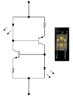
The 50 V fets should be okay since they seem to be protected with zener diodes, but it's hard to tell on that picture. They are using the fet as a CCS, but they have to be selected for whatever current you want (Idss). Therefore, just any fet of that type number will not do.
I'll try to help you out there.
-Chris
Can you email me a higher res. copy of that. I just suffered through another Pioneer reg. design (technician induced malfunction).
The 50 V fets should be okay since they seem to be protected with zener diodes, but it's hard to tell on that picture. They are using the fet as a CCS, but they have to be selected for whatever current you want (Idss). Therefore, just any fet of that type number will not do.
I'll try to help you out there.
-Chris
If you click on the link, it comes up as fairly low-rez. You may have to click on the pic once or twice to force ImageShack to resize it to the proper size (2460 x 1923, which will give you as much rez as you can possibly need).
Certainly I understand that the FET's can vary widely in Idss, but the schematic doesn't give me a clue as to the current that should be running through the FET. The two that I received from Consolidated both were fairly close to 2mA when they were installed in the circuit, which seems reasoinable, but if all Pioneer wants is a current source there, I can come up with something better if I need to...even a current regulator diode...but I've no clue as to the required current.
Maybe that is unnecessary, but I'm trying to undertand why it worked for a week then blew up. ...and what I can do to see that it is fixed for good.
Hi Glenn,
Duh! Okay, now I can read it. Thanks for the hint. Sometimes clicking the image gives you an ad for the image hosting service.
So, the R211, D209, D208, Q206, and R214 setup (and the negative side equivalent) is to limit the voltage across the fet at startup. R211 will limit the current to a safe value. We only expect to see 0.047 uF there so the time constant is very short. 2 mA seems reasonable.
The 1W zeners were possibly cheaper but I've seen Japanese companies use 500 mW sizes often when it should be 1W. In this case they may be trying to reduce the temperature dependence on the voltage. You will find that it's strongly positive. Also, if this PCB is mounted upside down (Pioneer classic stupidity), you may need the 1W due to temperature derating.
If you have high ripple on your +80V reg line, you either have low +106V (you measured it) or a transistor in wrong or leaky. I suspect Q210 is very leaky but measures the diode junction check okay. Measuring across R210 and R212 will tell you what the current draw is.
-Chris
Edit: Make sure that the voltage drop across R211 is zero, no current flow. If a zener was in backwards it could cause the positive regulator to fail. Also, check the filter caps on the 80 V rails on the amp section as they may be leaky and drawing too much current.
I can see the purpose of the two 24V zeners now (thank you), but why the current source? Guess I'm simply not familiar with a current source used like this in a regulator...anatech said:So, the R211, D209, D208, Q206, and R214 setup (and the negative side equivalent) is to limit the voltage across the fet at startup. R211 will limit the current to a safe value. We only expect to see 0.047 uF there so the time constant is very short. 2 mA seems reasonable.
I can easily swap 1W 24V zeners for D208~D211. But for D214 and D215, I was using 18V and 17V 1/2W zeners. Seems the 17V 1W zener is a no-show...I'd have to go to a 20V and a 15V zener to get my 35V. Not as 'neat' as a 17V and an 18V, but it would get the job done.The 1W zeners were possibly cheaper but I've seen Japanese companies use 500 mW sizes often when it should be 1W. In this case they may be trying to reduce the temperature dependence on the voltage. You will find that it's strongly positive. Also, if this PCB is mounted upside down (Pioneer classic stupidity), you may need the 1W due to temperature derating.
Q210 is also a new On-Semi MJE15032. Yes...I need to measure the current across R210 (but for frustration reasons I've set this whole thing aside for a few days).If you have high ripple on your +80V reg line, you either have low +106V (you measured it) or a transistor in wrong or leaky. I suspect Q210 is very leaky but measures the diode junction check okay. Measuring across R210 and R212 will tell you what the current draw is.
Zeners are in correctly, and for the 5 or 6 days that I was running, I had measured the voltage across R211 in an effort to see how the whole thing worked...I got 0.000V. RE: The amp section. I completely unplugged the amplifier driver boards (at least Pioneer made that easy), and the ripple was unchanged. So there was essentially no load on the +/-80V supply except the current stolen by the +/-34V regulators and fed to the preamp. Once the regulator is running againMake sure that the voltage drop across R211 is zero, no current flow. If a zener was in backwards it could cause the positive regulator to fail. Also, check the filter caps on the 80 V rails on the amp section as they may be leaky and drawing too much current.
") goodbad: ), I'll be disconnecting the output of the +/-34V and verify that here is where the problem lies (and it could be something as simple as a bad Q214 and/or Q216 on the +34V regulator).
goodbad: ), I'll be disconnecting the output of the +/-34V and verify that here is where the problem lies (and it could be something as simple as a bad Q214 and/or Q216 on the +34V regulator).Thanks Chris!

Hi Glenn,
This is your regulator voltage reference. Most of the drift will be due to ambient temperature increases. Upside down power supply.
I'm wondering about C216 and C218. If either were leaky as they got warmer (especially C216), they could cause trouble. C216 could force D208 and D209 into conduction and lower your regulated output. Not nice and hard to catch. It would also lower your +34 V supply a little.
Take it easy Glenn!
-Chris
A current source has a much higher effective resistance than a resistor. Therefore you get much higher raw supply noise rejection. Also, your output voltage will be much more stable with varying input voltage and load current. All of these are pretty clear winners, so they used the concept. They used a fet because it approximates a CCS, same with a constant current diode. I design using an LED voltage reference and BJT for much higher performance. Cascoding this increases the AC resistance even more and extends the high frequency effectiveness.but why the current source?
Good idea so they can handle the turn on surge better.I can easily swap 1W 24V zeners for D208~D211.
Why not try a 35 V 5W zener? They are not expensive and it would be neater.But for D214 and D215, I was using 18V and 17V 1/2W zeners.
This is your regulator voltage reference. Most of the drift will be due to ambient temperature increases. Upside down power supply.You're smarter than I am!(but for frustration reasons I've set this whole thing aside for a few days).
I'm wondering about C216 and C218. If either were leaky as they got warmer (especially C216), they could cause trouble. C216 could force D208 and D209 into conduction and lower your regulated output. Not nice and hard to catch. It would also lower your +34 V supply a little.
Yes, good thought.I'll be disconnecting the output of the +/-34V and verify that here is where the problem lies (and it could be something as simple as a bad Q214 and/or Q216 on the +34V regulator).
Take it easy Glenn!
-Chris
The Vds of 2SK34 found on the internet is variable. Some sources say that it's only 30 volts. The Pt is 150mW for sure.
http://www.minor-audio.com/data/2SK/2SK0011-0100.htm
http://www.datasheets.org.uk/search.php?q=2sk34&sType=part&ExactDS=Starts
I tend to think that it's vulnerable to be used here.
http://www.minor-audio.com/data/2SK/2SK0011-0100.htm
http://www.datasheets.org.uk/search.php?q=2sk34&sType=part&ExactDS=Starts
I tend to think that it's vulnerable to be used here.
Hi housing,
I'll bet the originals are good for 50V. Protection is running close at 48V and tolerances could push it over. That's the hell that is Pioneer.
A resistor in series with the fet between the drain and supply would share voltage and not have any bad effects (not significant anyway) and extend the saftey zone. A zener would acomplish the same thing.
-Chris
Max voltage can be very high, since the two transistors split the C-E voltage necessary to get your required current. A couple of high voltage transistors and I don't see why this wouldn't work up to a couple hundred volts.
I liked these since it was only two terminals. Higher parts count, but back when I was having the boards made I needed a two-terminal solution.
I've used these a few times, and the original design called for LED's, and that's what the mini-schematic shows. In practice, I found too much variation in LED voltage, and I had been sticking two series'd 1N4148 diodes in there instead.
I could do this...shoot for about 2mA?? That sound right?
The current source is also needed to start-up the regulator. With zero output voltage you get zero current through the 'error amp' transistor, getting you zero output voltage so you need something to initially start the thing, but present a very high dynamic resistance so it does not inject ripple. Given that, I would expect the FET(s) was leaking, which gave you the high ripple.
Honestly, I would dump the FETs and put in your CCS, the FETs were probably selected for Vdsmax.
One more thing - check D213/214. These are there to prevent excessive reverse voltage on the B-E juntions at startup (potentially -35V - sure to destroy the transistors).
so you need something to initially start the thing, but present a very high dynamic resistance so it does not inject ripple. Given that, I would expect the FET(s) was leaking, which gave you the high ripple.Honestly, I would dump the FETs and put in your CCS, the FETs were probably selected for Vdsmax.
One more thing - check D213/214. These are there to prevent excessive reverse voltage on the B-E juntions at startup (potentially -35V - sure to destroy the transistors).
Thank you... So, I could probably dump R211 & R213 and D208~D211 too. If their only job is to protect the FET, then seems like they'd serve no purpose if the FET is gone.ilimzn said:The current source is also needed to start-up the regulator. With zero output voltage you get zero current through the 'error amp' transistor, getting you zero output voltage
Honestly, I would dump the FETs and put in your CCS, the FETs were probably selected for Vdsmax.
Will do.One more thing - check D213/214. These are there to prevent excessive reverse voltage on the B-E juntions at startup (potentially -35V - sure to destroy the transistors).
Hi Glenn,
-Chris
That is true. Bye Bye zeners and one potential failure point.If their only job is to protect the FET, then seems like they'd serve no purpose if the FET is gone.
-Chris
Hi,
I've been following this thread and learnt some things from the people who replied.All assumptions seem logical and worth investigating,that's part of troubleshooting.
I have always thought that such repair was complicated because of the theories and facts we learn.Then I realised one important fact which is that the equipment once worked as designed with the original parts.
So the golden rule of repair is to use the original parts if possible or it's exact equivalent specification in the right location .
From the schematic I noticed that Q208,209 originally is 2SA628A 0.1A rating is replaced by one(2sc1509 and it's pnp part) rated at 0.5A.Based on my previous experienced of another amplifier that using a higher rated current part in the 'wrong" place in the circuit will have "catastrophic" consequence as I generally assumed a higher rated part is better and more reliable but I was wrong as the hfe,current and voltage play an important role in the operation of the device.If one is careless you will experience smoke or worst fire! .
Hope this helps.
Hi singa,
I you have a good understanding of the circuitry you can make substitutions successfully. In this case, everything has been done properly by Glenn. There is something else at play. Pioneer also tends to design power supplies on the edge. They wanted them to die after a while. Mnany other manufacturers are guilty of this. JVC ran National chips at bipolar 8V when they were rated at bipolar 6V (abs max.). I had to drop the voltage going to the chip to keep those expensive things from failing. I forced JVC to cough up for the chip itself.
Another thing you didn't mention. A new part isn't always a good part. I always test new parts.
-Chris
I agree with you there.If one is careless you will experience smoke or worst fire! .
I you have a good understanding of the circuitry you can make substitutions successfully. In this case, everything has been done properly by Glenn. There is something else at play. Pioneer also tends to design power supplies on the edge. They wanted them to die after a while. Mnany other manufacturers are guilty of this. JVC ran National chips at bipolar 8V when they were rated at bipolar 6V (abs max.). I had to drop the voltage going to the chip to keep those expensive things from failing. I forced JVC to cough up for the chip itself.
Another thing you didn't mention. A new part isn't always a good part. I always test new parts.
-Chris
No, a 2SA777 was used. You misread. And in this case, higher voltage, current, hfe, and power rating are a good thing.I noticed that Q208,209 originally is 2SA628A 0.1A rating is replaced by one(2sc1509 and it's pnp part)
anatech said:JVC ran National chips at bipolar 8V when they were rated at bipolar 6V (abs max.). I had to drop the voltage going to the chip to keep those expensive things from failing. I forced JVC to cough up for the chip itself.
Another thing you didn't mention. A new part isn't always a good part. I always test new parts.
-Chris
Hi Chris,
I did'nt know they did this! You are a consumate repairman.
EchoWars said:No, a 2SA777 was used. You misread. And in this case, higher voltage, current, hfe, and power rating are a good thing.
Sorry echowars if I've misread your post.

- Status
- This old topic is closed. If you want to reopen this topic, contact a moderator using the "Report Post" button.
- Home
- Amplifiers
- Solid State
- Pioneer SX-1980 Regulator Driving Me Insane!