
anatech said:Hi ilimzn,
Yes.
Good advice as always. I thought that D213 / 214 would possibly conduct on shut down, but not startup. I might learn something new here. What am I missing on startup?
Besides, diodes normally fail short.
-Chris
Actually, you are right, this is the main concern, where the 35V power supply caps are left charged while 85V supply may get depleted before that. However, on re-start (on/off/on) or brownout, you can get the same thing. Essentially, whenever there is voltage present on the 35V zener and output of 85V supply is 'shorted', i.e. caps need charging, so base of error amp transistor is below the zener voltage. Typically, about 5-8V is the reverse breakdown voltage for BE junctions. I don't remember exactly what the reason is (re doping and process) but I do recall there was one, (experience definitely proves it!) that reverse-biassed BE junctions cannot withstand any great current - they become leaky.
EchoWars said:Max voltage can be very high, since the two transistors split the C-E voltage [snip]
Be carefull here! Each transistor sees a Vce that is essentially the full supply (minus two LED dros).
Jan Didden
Hi ilimzn,
I design my regulators with that diode for the same reason, and a reverse biased diode across the pass element.
Hi Jan,
-Chris
They sure do, and don't forget noisy even if they don't fail that bad. Diff. pair transistors when an amp goes DC is a good example of this.Typically, about 5-8V is the reverse breakdown voltage for BE junctions. I don't remember exactly what the reason is (re doping and process) but I do recall there was one, (experience definitely proves it!) that reverse-biassed BE junctions cannot withstand any great current - they become leaky.
I design my regulators with that diode for the same reason, and a reverse biased diode across the pass element.
Hi Jan,
That's what I was thinking too. Still, looks like a nifty little circuit.Be carefull here! Each transistor sees a Vce that is essentially the full supply (minus two LED dros).
-Chris
Sorry...figured this thing out ages ago. Still, it isn't too tough to put transistors in there that can handle the voltage that they will see.janneman said:Be carefull here! Each transistor sees a Vce that is essentially the full supply (minus two LED dros).
Jan Didden

Yes...Happy New Year!!
I stayed sober, and came home to get some work done.")
Anyway, I built the two small current sources using Zetex ZTX694B and ZTX795A transistors, 665 ohm resistors, and two 1N4148 diodes in place of each LED in the above schematic. This gives about 2.1mA output on my cheap 1A bench supply, using the +/-15V to power it.
Both of them exhibit a quirk though...they don't always 'start up' on their own (on the bench supply anyway). About 1/2 the time, I can fire up the supply, and no current flows. If I briefly touch the back of the circuit board (solder side), it takes off and works fine. It's like they need a jump start to get current flowing.
Any thoughts on this?
I stayed sober, and came home to get some work done.
Anyway, I built the two small current sources using Zetex ZTX694B and ZTX795A transistors, 665 ohm resistors, and two 1N4148 diodes in place of each LED in the above schematic. This gives about 2.1mA output on my cheap 1A bench supply, using the +/-15V to power it.
Both of them exhibit a quirk though...they don't always 'start up' on their own (on the bench supply anyway). About 1/2 the time, I can fire up the supply, and no current flows. If I briefly touch the back of the circuit board (solder side), it takes off and works fine. It's like they need a jump start to get current flowing.
Any thoughts on this?
Startup resistor
Hi,
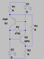
the german magazine elrad published this configuration in January 1988. They inserted a startup-resistor R3 to ensure a current through the diodes. An additional resistor R4 was used to compensate the small raise of current with increasing voltage even to obtain a negative source resistance. LED may be better for temperature effects than 2 diodes in series because TC of LED and transistors are similar values.
Check Design Note 4 on: http://www.zetex.com/3.0/3-8-2.asp
regards,
Onra
Hi,
the german magazine elrad published this configuration in January 1988. They inserted a startup-resistor R3 to ensure a current through the diodes. An additional resistor R4 was used to compensate the small raise of current with increasing voltage even to obtain a negative source resistance. LED may be better for temperature effects than 2 diodes in series because TC of LED and transistors are similar values.
Check Design Note 4 on: http://www.zetex.com/3.0/3-8-2.asp
regards,
Onra
Attachments
Hi Glenn,
I use LEDs for that exact reason.
Your current source provides the operating current for the error amp and output drive. Therefore the temperature effects are important as long as the quality of your regulator is important. You should see a performance increase with your BJT CCS. Freedom from over voltage is a very nice side benefit.
-Chris
EchoWars said:Thank you!
The temperature effects are likely not important if, as ilimzn suggests, the main function of the current source is to get the regulator jump-started at turn on. Still, I can see the wisdom of using an LED rather than the diodes.
Well, it sets part of the current through the error amp and zeners (the other part being base current of the pass transistor). How important this current source is, depends on what portion ot the total current it provides - the problem being, that it's non-infinite impedance injects a part of the input ripple into the error amp. Even so, this current source should be much better then a single FET, although, your startup cap does make it worsen at HF. Still, IMHO it's not going to be a major problem in the particular application, the major component is LF, and for the HF part, your regulator does have output caps. I do like the nice schematic referenced above, though, because even though it reduces the equivalent impedance of the CCS, at least it adds a less reactive component with better controlled value in parallel.
Well, I rebuilt one of the current sources with plain-Jane green LED's instead of the dual-diodes. Its behavior is much improved...starts up every time without a resistor or cap between the transistor bases, and bleeds off normally as the supply voltages decay instead of shutting down abruptly like the diode-referenced regulator did.
Wondering if I should join the bases with a 470K resistor anyway, just to ensure that it doesn't fail to start up?
Wondering if I should join the bases with a 470K resistor anyway, just to ensure that it doesn't fail to start up?
Well, damn. The first one starts every time. The second one has a 'delay' of 2 seconds or so about every other time it gets powered on before current flows. They are built identically, so I dunno what's up.
The boards I have for these is tiny. My regular 1/4W resistors are too big. I need some of the super-mini 1/4W Panasonic resistors (body is a little over 3mm long). I'm going to to have to order some 820K ones and see if that allows enough current to flow to get the job done.
Of course, that means another parts delay. Damn.
The 1M resistors between the bases of the transistors seem to have cured the start-up problems. I need to test them some more, but I think the issues are taken care of. If that's the case, I simply need to gather the courage to put this big pig back on the bench.
Seems to have hurt regulation a little bit...a change of 5V of supply voltage changes the current by about 10µA.
Seems to have hurt regulation a little bit...a change of 5V of supply voltage changes the current by about 10µA.
- Status
- This old topic is closed. If you want to reopen this topic, contact a moderator using the "Report Post" button.
- Home
- Amplifiers
- Solid State
- Pioneer SX-1980 Regulator Driving Me Insane!