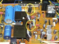
Well, the regulator is re-rebuilt, and the current sources are in. Works like a charm (but output is a tad low at about +/-75V...I don't really care much about that at this point). They are tiny little suckers, but still look kinda funny. I'm not sure what I'd think if I opened up a 1980 and saw these.
I had to disconnect the +34V line to get the +80V to come up. Something is dragging it down hard-core.
I'm done breathing solder fumes for the evening. I'll tackle it again tomorrow.
I had to disconnect the +34V line to get the +80V to come up. Something is dragging it down hard-core.
I'm done breathing solder fumes for the evening. I'll tackle it again tomorrow.
Attachments
There are two wires on each of the +34V and -34V connection posts. One pair go to the phono amp. The other go to the preamp, and daisy-chain to three boards...the tone amp, flat amp, and a filter board. I disconnected them all, and verified that everything with the regulator looks good. Then I connected the phono amp. No problem, all looks good. OK, so then I connect the other set of wires to the preamp boards. Everything still looks good. Hmmm...
The regulator on this receiver has been worked on many, many times, and at least once the guy working on it decided that the best way to fiddle with it was to desolder ALL the wires and completely remove the board. This is always a disaster with the brittle, solid-core, wire-wrapped connections that Pioneer was so fond of, and makes for some rather colorful re-soldering jobs. This one is no exception.
All I can figure is that there was a small solder blob that I couldn't see making contact between the +34V pin and the ground pin right next to it, since once I reworked the connections it all seems to work perfectly.
Makes me a little paranoid to see the problem disappear like that, but all I can do is to run it and see what happens...
After a couple of hours, all is still running fine.
I sure hate that hot regulator heatsink baking those caps. P*ss-poor design courtesy of Pioneer.
Anyway, I suspect that the 2.2mA current sources are not exactly the optimum value...the +80V supply comes up real slow. As a consequence of this, the speaker output relay takes a good 10 to 11 seconds to engage (the relay is driven by the PA3004 protection IC, which has its own 13V zener regulator powered from the +80V output). Unfortunately, I was unable to get anyone with a working 1980 to give me a voltage measurement across the 22 ohm resistor in the stock FET current source and had to go with what I measured on the replacment FET's. 5mA might be more like it, but there's no way in hell I'm disassembling this reg board again.
I'll run it for a week and see how it does. If it blows up again I may have to take a drive out to the Muddy Missouri River and delight in watching this thing make a really big splash as I heave it over the railing of the I-435 bridge.
Hi Glenn,
I wish I could help you more. I suspect that it is running now and your ripple levels have fallen to really low levels.
")
-Chris
I wish I could help you more. I suspect that it is running now and your ripple levels have fallen to really low levels.
Didn't I say that earlier? You may have too.I sure hate that hot regulator heatsink baking those caps. P*ss-poor design courtesy of Pioneer.
-Chris
I can't even see the ripple on the scope any more. Before, I was measuring almost 3V P-P of ripple on the +80V line, now all I see is 'mild fuzz' on the 80V line with the scope set to 50mV/div.
Like I said, if I did this again I'd likely step up the current source to 5mA and see if that allowed the 80V lines to come up a bit quicker. Other than the slow start-up times (which will remain as it is for lack of motivation to change), looks like this might be a nearly completed deal.
Like I said, if I did this again I'd likely step up the current source to 5mA and see if that allowed the 80V lines to come up a bit quicker. Other than the slow start-up times (which will remain as it is for lack of motivation to change), looks like this might be a nearly completed deal.
Hi Glenn,
At 2 mA, your error amp is dissipating about 100 mW, upping this to 5 mA increases the dissipation to 250 mW. These figures are only a touch high. Considering that the heat just hangs there, I don't think that is the answer.
C228 should be 0.047 uF and C216 should be 100 uF. Is it possible that either Q214 or Q216 has low gain or an E-B short? C216 does seem a little large for this location.
-Chris
The series pass transistors were replaced with On-Semi MJE15032's (and MJE15033's on the '-' side). Q214 is a high-gain Zetex ZTX694B. Q208 and Q212 are Zetex ZTX855's, and I measured gain at around 200 on them before I installed 'em. Virtually none of the transistors on the +/-80V and +/-34V regulators did not get replaced...I was not interested in doing this yet again and wanted a clean house.
The 0.047µf caps were even replaced with new Panasonic 400V film caps. All the electrolytics are new, and the values match the stock values.
The stock error amp transistor is a 2SC1318, rated for 625mW, so Pioneer may well have been pushing more current through it than I am.
I've measured the voltage drop across both R210 and R212, and calculated about 115mA current through each. This is pretty much in line with the current output figures given on the large full schematic that Pioneer includes in the service manual.
Why it comes up slow...I dunno. Not sure if I care either, since the bloody thing is working.
Hi Glenn,
Away with it!
-Chris
Derate for heat.The stock error amp transistor is a 2SC1318, rated for 625mW
That would not surprise me. Not a good design choice though.so Pioneer may well have been pushing more current through it than I am.
Probably better than it ever has.Not sure if I care either, since the bloody thing is working.
Away with it!
-Chris
Just as a quick postscript to this whole episode, I got another 1980 in here that needed some attention. When I got to the regulator, I decided to see what the stock current source measured. I saw about 50mV across the 22 ohm resistor, so it looks like Pioneer intended for the FET to be sourcing about 2mA...about the same value that I chose.
So the 2mA source I installed is not the reason for the slow start-up of the original 1980 I worked on. But...that one is now in Scotland, working well, and I doubt I ever see it again.
May it live long.
So the 2mA source I installed is not the reason for the slow start-up of the original 1980 I worked on. But...that one is now in Scotland, working well, and I doubt I ever see it again.
May it live long.
Hi Glenn,
I think you did a good job on that one. There are so many areas that could also be a problem, take your pick. I do think this was an excellent example on how to get around a problem and improve the performance as well.
-Chris
.......and never cross your threshold again!May it live long.
I think you did a good job on that one. There are so many areas that could also be a problem, take your pick. I do think this was an excellent example on how to get around a problem and improve the performance as well.
They like you!Just as a quick postscript to this whole episode, I got another 1980 in here that needed some attention.
-Chris
I like the layout, got a pix of the other side?
I have a slew of really nice little two-terminal boards designed for a current source. Perhaps now is the time to use a few of them.
Just saw this...sorry.
I'm down to making these little boards out of perfboard...all the nice house-fabbed boards are gone. And as far as keeping the whole deal cooler, might check out this thread: Pioneer SX-1980 Regulator Modification - AudioKarma.org Home Audio Stereo Discussion Forums
I'm down to making these little boards out of perfboard...all the nice house-fabbed boards are gone. And as far as keeping the whole deal cooler, might check out this thread: Pioneer SX-1980 Regulator Modification - AudioKarma.org Home Audio Stereo Discussion Forums
- Status
- This old topic is closed. If you want to reopen this topic, contact a moderator using the "Report Post" button.
- Home
- Amplifiers
- Solid State
- Pioneer SX-1980 Regulator Driving Me Insane!