Consider PSRR... Power Supply Rejection Ratio!
This schematic will have very poor values, resulting in hum direct from the power supply!
Onle solution is to use a regulated power supply, which isn't really great for at power amp.
For fun.... Try simulation 1 volt ripple on you supply rail. How much hum will this result in, on the output?? Remember that this hum will be there always, not depending on music volume!
Hurtig said:Consider PSRR... Power Supply Rejection Ratio!
Hurtig
we have already discussed PSRR, in this topic!
didnt you notice
")
Some suggestions, what can be done
to improve power supply rejection
has been implemented
... and from what have understood results has been very good!
Regards
lineup
http://lineup.awardspace.com/
jerluwoo said:Yes results were excellent on rejection, amplifier is very quiet now.
jerluwoo
I'd like to make my own version of your best version of this Class A Single End amplifier
What version you would recommend I start with?
In what post number? ( this is Post #64 )
What I will do,
is try it in my Electronics Workbench MultiSim, like you did.
Then I will add my own changes.
So get a lineup special version design, using whatever knowledge I have.
( I have built many Class A amps before, preamps & poweramps )
I hope you do not mind me using your schematics.
I will link to this topic, and tell you, jerluwoo,
are
The Original Idea Designer I will also present lineup special version of this simple class a
as project05 in my projects page:
http://lineup.awardspace.com/contents.html
credit to whom credit may belong
and regards from
lineup
http://lineup.awardspace.com/
Be my guest Lineup, this is what I began posting this circuit for. As for the best version it would be a toss up. The ccs version in post 58 is the most stable as far as bias and temprature drift and still retains a very good sound. The schematic of post 46 although drifts a bit, has a much more transparent or natural sound in the high end treble for a lack of a better way to explain it. Perhaps the circuit of 46 on a very good regulated supply may be the best for sound, or the circuit 58 for the best stability with very good sound as well.
Havn't gotten around to you last suggestions to reduce heat, but be aware also that the load the vas is driving is only around 700-900 ohms so I expected to need a fair amount of current to drive it added with the load resistor going to ground causes a need for 2 times the current from the ccs.
Also the output capacitor should be figured a bit higher value for low end cut off. Not sure if it has to do with no feedback for the output but the circuit seems to like larger than normal caps for the deepest bass, but the circuit has a -3db point near 7hz also, so it may just seem that way by perception.
So I decided to test my hybrid circuit this evening. I built a smaller unit just to test. Running it at only 15 volts it's only good for about 5 watts. But the wonderful news is that it started up and worked perfectly the first time. The sound is almost identical to its all ss counterpart. I've seen it said many times that tubes cannot push a bjt output stage but this little circuit has defied that saying. So heres the little simple thing that sounds really nice.
Attachments
jerluwoo said:Be my guest Lineup, this is what I began posting this circuit for. As for the best version it would be a toss up. The ccs version in post 58 is the most stable as far as bias and temprature drift and still retains a very good sound. The schematic of post 46 although drifts a bit, has a much more transparent or natural sound in the high end treble for a lack of a better way to explain it. Perhaps the circuit of 46 on a very good regulated supply may be the best for sound, or the circuit 58 for the best stability with very good sound as well.
Havn't gotten around to you last suggestions to reduce heat, but be aware also that the load the vas is driving is only around 700-900 ohms so I expected to need a fair amount of current to drive it added with the load resistor going to ground causes a need for 2 times the current from the ccs.
Also the output capacitor should be figured a bit higher value for low end cut off. Not sure if it has to do with no feedback for the output but the circuit seems to like larger than normal caps for the deepest bass, but the circuit has a -3db point near 7hz also, so it may just seem that way by perception.
right now control panel of my website has been down for 1 week
so no FTP uploads and new pages could be added
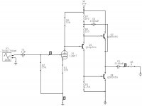
I will use what I call jlw-post58 schematic, and see what improvements can eventually be done.
See my attachment in this post.
About output electrolytic CAP and low corner frequency of amplifier.
Just as C1 ( 10uF ) together with R5, R6 ( 220k each ) form a high pass filter,
the output CAP together with nominal impedance of Loudspeaker
form another high pass filter.
Will let signals higher than a frequency f pass.
f, Hertz,
C, Farad
R, Ohm
f = 1/ ( 2x PI x C x R )
Input
C = 0.000010 F ( 10 uF ), R = 220k//220k = 110k
f = 1 / (2 x 3.14 x 0.00001 x 110000)
f ~ 0.145 hertz
so, if you use a better quality filmcap 1 uF, you still have rolloff freq
at like 10 x 0.145 hertz = 1.45 hertz
Output ( remember big electrolytic caps can have wide tolerances +-20% is not uncommon )
C = 0.0044 F, R = 8 Ohm
f = 1 / ( 2 x 3.14 x 0.0044 x 8 )
f ~ 4.523 hertz
If you can find high quality 1000 uF or 2200 uF you can try parallel them at output
instead of one big.
Your rolloff frequencies are already low enough, in my opinion.
Myself is often happy using like 5 hertz at inputs, and 10-15 hertz at outputs.
If there is any lack of bass it should not depend on your caps.
Now subjective impressions should go hand-in-hand with some
examining of the output signal in an OSCILLOSCOPE.
This will give a better hint, if there is something real.
lineup
Attachments
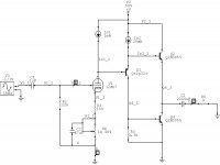
I already see one thing
you should try to change.
This is the value of R2, 1500 ohm.
Try lower this to 100 ohm ( I would go as low as 47 ohm! )
This will add like 6 mA in this stage ( current in Q3 )
To also add 6 mA in your CCS, just add a 100 ohm resistor in parallel across R3 ( 22 ohm )
0.600 volt / 100 ohm = 0.006 ampere = 6 mA
This R2 resistor has some importance to lower distortions.
Read Rod ESP Elliott experiments while construction of his very simple class a
Death of Zen (DoZ) - A New Class-A Power Amp
He started out by adding a resistor 3k3.
But if you look at his semi-final DOZ, using 2N3055
he now would use 100 ohm for this resistor
R5 in this Schematic
http://sound.westhost.com/p36-fig4.gif
Complete article, with some figures and some good things to learn and think about:
A New Class-A Power Amp - by Rod Elliott
Regards
lineup
Audio Amplifier Website
http://lineup.awardspace.com/
you should try to change.
This is the value of R2, 1500 ohm.
Try lower this to 100 ohm ( I would go as low as 47 ohm! )
This will add like 6 mA in this stage ( current in Q3 )
To also add 6 mA in your CCS, just add a 100 ohm resistor in parallel across R3 ( 22 ohm )
0.600 volt / 100 ohm = 0.006 ampere = 6 mA
This R2 resistor has some importance to lower distortions.
Read Rod ESP Elliott experiments while construction of his very simple class a
Death of Zen (DoZ) - A New Class-A Power Amp
Originally posted by Rod Elliott:
Some interesting things came to light during testing, especially when I included the resistor (R6) from base to earth on Q2. With no resistor, I measured a distortion of 0.15%, and this was almost completely 2nd harmonic. There was a very noticeable degradation of the positive going slope on a 10kHz square wave, and a fairly low slew rate resulted. Adding the resistor improved this dramatically, and reduced the distortion to 0.05% - but it was now almost completely 3rd harmonic.
He started out by adding a resistor 3k3.
But if you look at his semi-final DOZ, using 2N3055
he now would use 100 ohm for this resistor
R5 in this Schematic
http://sound.westhost.com/p36-fig4.gif
Complete article, with some figures and some good things to learn and think about:
A New Class-A Power Amp - by Rod Elliott
Regards
lineup
Audio Amplifier Website
http://lineup.awardspace.com/
I spent some time examining this resistor's role in things and settled upon this value because it gave the most even bias and ac currents when compared with the top transistor. As I recall when sim'ed lowering this below 1k or so caused a large imbalance between the ac current output of the top and bottom transistor. This may not be the case now with the ccs in place.
quote:
This may not be the case now with the ccs in place.
A constant current source instead of resistors, even with bootstrap cap
changes things a whole lot.
If you change to 100 ohm ( from 1500 )
then you adjust the current source for to get same idle current in output stage.
As told,
putting a like 100 ohm or 120 ohm resistor in parallel across R3 ( now 22 ohm )
will do this balancing.
I would be very surprised, if not the amplifier would perform better
after this first upgrade I have suggested.
Within a few days, I will setup jlw-post58 circuit into my ELW Multisim
and start exploring what possible improvements can be done.
I might also try some other transistors in a few places.
I have a couple of favourites: BD139 and MJE15030
It is not about to change the amplifier to something else.
I trust you, it is good enough to play music very well!
It is about trying to further change small details and values, for an optimal result.
Regards
lineup
I have modeled with the mje15030 for outputs and they're higher overall hfe compared to the 3055's reduced the amount of current needed through the "phase splitter" section to half that needed with the 3055, a worthy upgrade, I am just working with what I have on hand so I model with 3055 to build by. I also did some modeling to reduce power consumption in the input stage as well. Changing to 470 emitter resistor and 4.7k load resistor lower the power consumed by the stage considerably so that a good quality small signal trans can be used here. The trick is to get the correct current for symetrical clipping and the input voltage divider values must be reconfigured to get the correct adjustment range for setting vout.
Been playing with the tube hybrid for a bit and neglecting this circuit lately but have begun working with it again. The next improvement found was the oppisite of what you had thought about the resistor at the base of the bottom output trans Lineup. Increasing this resistor to between 3.3k and 4.7k then adding a second resistor from the base of the top output trans to ground of the same value showed a decrease of around .1% thd. This also made a noticable difference in the amplifier's ability to control the cone of the woofers in my speakers.
Try this:
R2 = 50V/(Imax*HFEQ2)
R4<=0.1/(sum of "dirty" currents of CE of hot Q1 and of dirty current of CB of hot Q2)
Imax = 25V/Rload
Idle current will be 1/2 of a max peak current, it means that it will be 50% efficient A - class amplifier with "adaptive" bias.
...But Q4 needs to have one more emitter follower for this values. Or use HEXFET instead of it, and you'll have exactly what I currently use in my class A amp.
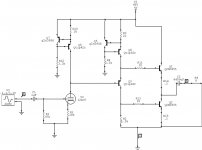
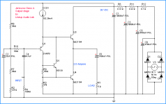
Jerluwoo MJ21194 Output Stage - by Lineup Audio Lab
I promised earlier I would try to make an improved version
of this good simple Class A. This idea of jerluwoo.
And here it is.
See Attached Shematic!
Using one transformer 30 Volt, >=100 VA ( 150-200VA recommended ) per channel.
For one transformer feeding stereo, I we would use 30 Volt 200-400VA.
If you find 2x15 Volt transformer, this of course works the same.
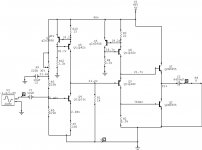
Simulated performance.
I tried using MJ15024, but gave a little more distortion.
I also tried using MJL3281A ( 4 times faster than MJ21194 ), and this gave a little lower distortion than MJ21194.
This was only at lower levels.
Because at around 8 Watt RMS and above distortion was WORSE than MJ21194
due to unsymmetrical overshooting behavior.
As I didnt really know how to add a cap filter to stop this overshooting
I simple went back to using MJ21194 for this design.
At 2.0 Ampere, this output stage likes 5-6 Ohm speaker the best.
In 5 Ohm load:
--------------------------
0.200% THD: 21.53 WattRMS, 10.40 Vrms = 14.67 Vpeak 2.94 Apeak
0.100% THD: 14.10 WattRMS, 08.40 Vrms = 11.87 Vpeak 2.38 Apeak
0.020% THD: 01.00 WattRMS into 5 Ohm
One thing I have not tested, is how stable amplifier is in Capacitive Load.
Professor Leach told in description of his LowTIM Amplifier,
that worst capacitive test he knew, was to put one 2.2 uF cap parallel to the 8 Ohm load.
And his LowTIM amplifier passed this worst case test!
Regards
lineup
I promised earlier I would try to make an improved version
of this good simple Class A. This idea of jerluwoo.
And here it is.
See Attached Shematic!
Using one transformer 30 Volt, >=100 VA ( 150-200VA recommended ) per channel.
For one transformer feeding stereo, I we would use 30 Volt 200-400VA.
If you find 2x15 Volt transformer, this of course works the same.
Simulated performance.
I tried using MJ15024, but gave a little more distortion.
I also tried using MJL3281A ( 4 times faster than MJ21194 ), and this gave a little lower distortion than MJ21194.
This was only at lower levels.
Because at around 8 Watt RMS and above distortion was WORSE than MJ21194
due to unsymmetrical overshooting behavior.
As I didnt really know how to add a cap filter to stop this overshooting
I simple went back to using MJ21194 for this design.
At 2.0 Ampere, this output stage likes 5-6 Ohm speaker the best.
In 5 Ohm load:
--------------------------
0.200% THD: 21.53 WattRMS, 10.40 Vrms = 14.67 Vpeak 2.94 Apeak
0.100% THD: 14.10 WattRMS, 08.40 Vrms = 11.87 Vpeak 2.38 Apeak
0.020% THD: 01.00 WattRMS into 5 Ohm
One thing I have not tested, is how stable amplifier is in Capacitive Load.
Professor Leach told in description of his LowTIM Amplifier,
that worst capacitive test he knew, was to put one 2.2 uF cap parallel to the 8 Ohm load.
And his LowTIM amplifier passed this worst case test!
Regards
lineup
Attachments
I think you are using the same sim as I am (electronics workbench multisim). I have no trust in this sim for anything other than if a circuit wont blow up (shady on that anyway), but my findings for the original output stage alone were .015% 30v supply at 10v rms output into 5 ohms using the mjl21194 for outputs. My distortion figures quoted earlier in the thread were for the entire circuit. The voltage amplifier/ first stage contributed nearly all of that distortion. The amount of distortion at full output is greatly influenced by where vout is sitting unfortionately. That may be the largest downfall to this circuit, having to add distortion to stabilize thermal drift.
- Status
- This old topic is closed. If you want to reopen this topic, contact a moderator using the "Report Post" button.
- Home
- Amplifiers
- Solid State
- My simple class a approach