hello
yes, this amplifier is good
... and perfect project for experimenting
and gain understanding of Solid State Transistor designing.
How those behave and what resistor values they need for support.
For best performance.
Remember, when this topic started, jerluwoo was 'a newbie'
today he is at level with many diyaudio members with several years of experience.
-------------------
Two things:
1. You could try adding a emitter resistor for Q2 (bottom output transistor)
Use same value as in Q1 emitter: 0R1 = 0.1Ohm
Should be attached, of course, from Q2 - Emitter to Ground 0V.
This may change the clipping point and behavor a bit.
My own testings, say that,
if you run output stage with a bias of for example 1.0 Ampere
the output will begin distort at a level of 75% of this.
That is 0.75A out in this example.
And this means a peak output voltage of 0.75A x 8 Ohm = +/- 6 Volt peak.
This is RMS Volt output: 0.707 x 6.0 =~ 4.24 V RMS
And power level if using 8 Ohm loudspeaker will be:
2.25 Watt RMS .... ( 4.24x4.24/ 8ohm )
If this 8 Ohm LSP has got SPL sensitivity 92dB / Watt
the resulting 'Sound Pressure Level' we hear (at 1.0 meter distance from 1 loudspeaker) will be:
92dB + [ LOG( 2.25 watt rms ) x 10 ] = 95.5dB
Something like being close to a JUMBOJET ENGINE airplane taking off
=================================
2. Regarding hum & better power supply.
The bigger the transformer, the less ripple and hum.
The better filtering, see my post above, the less ripple.
If you use for example +40V DC supply and set output stage bias 1.5A
this will mean a power of 1.5A x 40VDC is taken from trafo.
As a rule, it is good if Transformer is at least 2-3 times this:
for 60 Watt idle in amplifier
this would give something like:
120VA - 180VA rated transform ( e.g. 30 VAC, 4A or .... 28VAC, 6.5A )
=============================================
A practical example. Doing the math and get the numbers right.
Now a good transformer for this project, for my own version .
What would it be like?
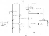
schematic:
http://www.diyaudio.com/forums/attachment.php?s=&postid=1036543&stamp=1161488807
Data we have:
- The trafo is 30VAC, before 4 rectifier diodes.
- The taken power by this Class A amplifier is
~ 40VDC x 2.0 Ampere (for one mono channel)
.... gives like ~ 80 Watt
--------------------
I would probably try to find something like 250VA transformers.
Two of them for a stereo, dual mono setup.
Two totally separate amp modules, with each its own power supply+transformer.
2x28 VAC, 250 VA .. I might find
I would need to parallell those two windings. In each transformer.
--------------------
The other way, buying only one transformer, would be:
Buy one 2x28 VAC, 400VA toroid transformer
Will give like 200VA in each winding.
And so I use this trafo for STEREO.
One winding per amplifier.
With two separate Rectifier and electrolyt capacitors filters.
As 400VA is 2.5 times 80+80 Watt,
I think it would be enough strong transformer to feed two mono amplifiers taking 2.0A x 40 VDC
Regards
lineup
yes, this amplifier is good
... and perfect project for experimenting
and gain understanding of Solid State Transistor designing.
How those behave and what resistor values they need for support.
For best performance.
Remember, when this topic started, jerluwoo was 'a newbie'
today he is at level with many diyaudio members with several years of experience.
-------------------
Two things:
1. You could try adding a emitter resistor for Q2 (bottom output transistor)
Use same value as in Q1 emitter: 0R1 = 0.1Ohm
Should be attached, of course, from Q2 - Emitter to Ground 0V.
This may change the clipping point and behavor a bit.
My own testings, say that,
if you run output stage with a bias of for example 1.0 Ampere
the output will begin distort at a level of 75% of this.
That is 0.75A out in this example.
And this means a peak output voltage of 0.75A x 8 Ohm = +/- 6 Volt peak.
This is RMS Volt output: 0.707 x 6.0 =~ 4.24 V RMS
And power level if using 8 Ohm loudspeaker will be:
2.25 Watt RMS .... ( 4.24x4.24/ 8ohm )
If this 8 Ohm LSP has got SPL sensitivity 92dB / Watt
the resulting 'Sound Pressure Level' we hear (at 1.0 meter distance from 1 loudspeaker) will be:
92dB + [ LOG( 2.25 watt rms ) x 10 ] = 95.5dB
Something like being close to a JUMBOJET ENGINE airplane taking off
=================================
2. Regarding hum & better power supply.
The bigger the transformer, the less ripple and hum.
The better filtering, see my post above, the less ripple.
If you use for example +40V DC supply and set output stage bias 1.5A
this will mean a power of 1.5A x 40VDC is taken from trafo.
As a rule, it is good if Transformer is at least 2-3 times this:
for 60 Watt idle in amplifier
this would give something like:
120VA - 180VA rated transform ( e.g. 30 VAC, 4A or .... 28VAC, 6.5A )
=============================================
A practical example. Doing the math and get the numbers right.
Now a good transformer for this project, for my own version .
What would it be like?
schematic:
http://www.diyaudio.com/forums/attachment.php?s=&postid=1036543&stamp=1161488807
Data we have:
- The trafo is 30VAC, before 4 rectifier diodes.
- The taken power by this Class A amplifier is
~ 40VDC x 2.0 Ampere (for one mono channel)
.... gives like ~ 80 Watt
--------------------
I would probably try to find something like 250VA transformers.
Two of them for a stereo, dual mono setup.
Two totally separate amp modules, with each its own power supply+transformer.
2x28 VAC, 250 VA .. I might find
I would need to parallell those two windings. In each transformer.
--------------------
The other way, buying only one transformer, would be:
Buy one 2x28 VAC, 400VA toroid transformer
Will give like 200VA in each winding.
And so I use this trafo for STEREO.
One winding per amplifier.
With two separate Rectifier and electrolyt capacitors filters.
As 400VA is 2.5 times 80+80 Watt,
I think it would be enough strong transformer to feed two mono amplifiers taking 2.0A x 40 VDC
Regards
lineup
Great to hear your having success with this little circuit. The best part is the output section, I've used it in all kinds of configurations of voltage drive into it and it works great every time. My current favorite little amp to listen to is a tube frontend into this output stage, I posted it a while back in tubes secton. It is very true about the most basic circuit about the nice sound it makes, but sadly it seemed to my perception that when the current source was added in the first stage it seemed to lose a little of that magic. Not to say that it made it sound bad, just not as musical ie. less nice 2nd order distortion. Please keep us updated of your findings.
Just something quick and handy to do with this output stage is to drive it with a portable cd player or even a pc sound card to drive an efficient speaker. Using split rail supply we can simplify the circuit considerably and still retain excellent stability even under very harsh loads. Depending on the quality of the pot used offset drift is practically nil. the only dissadvantage is a varying input impendance according to needed offset adjustment, although it will ussually be a small area between 8-12k.
Attachments

jerluwoo said:
Depending on the quality of the pot used offset drift is practically nil. .
This is my own experience too, jerluwoo
When using a true Class A amplifier, ( this goes for PreAmplifiers as well ):
After the circuit, including chassis etc.
has warmed up fully ( can take some half an hour or even hour, sometimes )
... it will stay VERY STABLE regarding DC-offset and any other parameter
... actually more precise, than any Class B or AB amplifier can and will be
this comes from the fact, that temperatures in non-Class A amps
are strongely variable
depending on actual Power Output
Regards
lineup
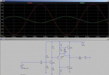
Since I'm bored I might as well just throw another setup with this output stage that worked well. Frequency comp values were trial and error on the proto type circuit but it performed excellent. It sims very low thd, and the sound is very, well plain to me, i like the harmonic generator amps i suppose . But still it was a very good performer.
. But still it was a very good performer.Attachments
And before I forget, The clipping issue can be attributed to the voltage level at the emitter of the input transistor. It can not swing any further negative than this point. I also found this behavior. Clipping point will happen at different voltage input based on the gain of the input transistor which is probably self explanitory.
Its the positive half of the output im haveing clipping problems with..
Checking with signal generator and osciliscope gives very similar results to what i get in the sim so i'll post a screenshot of what im talking about..
I have removed the emmiter resistor from the output in my prototype, dosnt apear to affect performance atall acording to my measurements, there isnt really any change in the sound either so i think i'll leave it out (keep it as simple as possible at the moment)..
Attachments
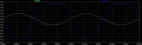
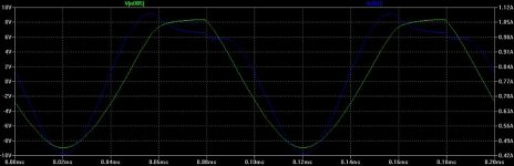
if i decrease the value of R9.. The clipping gets better.. to the point that eventually it goes away (but the current through the output stage ends up at stupid levelss even for a class A)... You can see exactly what is going on in teh following diagram (this is with R9 at 280Ohm) blue is current through Q1 and green is output...
Attachments
DoomPixie said:and now it works....
but i hate to think what the idle current through the output stage is going to be like....

first,
right you are,
the emitter resistor of upper output transistor
is not good for much ... it is not necessary.
Such an emitter resistor in Q2, would have a bit more effect.
But I am not sure if is necessary to put one in Q2 emitter.
Probably can work without.
But one thing could be useful, at least while experimenting (you can remove 0R1 resistor later):
If measure voltage across 0R1 emitter resistor, you can see what current is in OUTstage.
second,
Your Trick with C3, is great thing! (AKSA uses this bootstraping CAP in his amp kits)
third,
R1 + R9 and R4 values, will all effect the current in output
-> lowering R1+R9 values, will increase CURRENT
-> lowering R4, will decrease, make less current in output
One way would be:
Make R1+R9 such as you get a bit TOO MUCH current in output.
Then replace R4 with
for example:
one resistor 470 Ohm + one trim pot 470 Ohm (=940 Ohm total )
Then you turn down value of Trimpotentiometer,
until you get a 'normal bias level' in output.
regards
lineup
the only way i found to get rid of the clipping useing the transistors i chose was to increase the current..
I am thinking mabey it would work better with different transistors though, to be honest i just put it all in the sim useing transistors i know i have and then i built it around them.. i think it is Q3 that could do with changeing, the signal after Q4 is always good, it is when it goes through Q3 that i get problems..
any ideas?
Also for power supply is toroid better or worse? I want to make monoblocks...
Cheers,
Owen
What is the voltage sitting between the output trans. The only trouble I could find would be vout sitting too high causing the postive end to clip. The point at q1's base also sits a vbe drop above and will clip slightly before the vas. I would recommend adding a high value pot 220k or more above r7 to adjust vout and lower the value r7 say 47k or lower or higher to get the adjustment range needed depending on the beta of q4. Your increase in current probably lowered where vout is sitting which remedied the clipping. also increase r4 to 2.7k, this biases q2 higher and will help lower vout as well. Vout is optimal at 1/2 supply plus the voltage at the emitter of q4. As for the bootstrap choose a value for r9, say 220 ohms and replace r1 with 300 ohm pot to adjust bias setting, then adjust vout with the pot added above r7 when you have the idle current you want.
As for the power supply the only thing you need to worry about other than your transformer supplying enough voltage and current is filtering. I used a simple CLC which was effective, but for best results if you plan to keep the circuit in its simplest form, the best supply would be regulated supply.
As for the power supply the only thing you need to worry about other than your transformer supplying enough voltage and current is filtering. I used a simple CLC which was effective, but for best results if you plan to keep the circuit in its simplest form, the best supply would be regulated supply.
DoomPixie said:
Also for power supply is toroid better or worse?
I want to make monoblocks...
Cheers,
Owen
.
Both E-type core and Toroid core trafos will work well.
I use both sorts,
when I can find some with fitting rating (size) & price.
In surplus sales, you can many times find great E-Type transformers.
They are a bit bigger and heavier than same rating Toroids.
Regards
lineup
------------------------------------------------------------
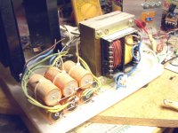
Attachment.
some of Lineup Audio Labs tansformers.
bought for very low price from a Surplus bargain sale several years ago.
.... I took my chance, when I had the opportunity!
These ones are 1 winding, 26 VAC 4 Ampere = 104 VA
Two of them will give: 2x26 VAC, 208 VA
Will output something like:
2x36 Volt DC at max 2.5 A, average output
The primary main input is one winding: 110 - 110 - 20 VAC
Which means, I can use input: 220VAC or 240VAC
and so adjust the resulting Ouput VDC a bit~, -10%
so it will output 32.4 instead of 36 Volt DC.
The Elyts in this picture, is also from a bargian sale:
RoE Axial, 4700uF 63V
I bought a large box of them ... think 50 pieces!
Attachments
See here a close up image of
these
Roderstein, ROE capacitors
in this Topic:
Why Dual mono?
http://www.diyaudio.com/forums/showthread.php?postid=1010128#post1010128
Here is my attached CloseUp picture, in 'dual mono' topic:
http://www.diyaudio.com/forums/attachment.php?s=&postid=1010128&stamp=1158794904
lineup
these
Roderstein, ROE capacitors
in this Topic:
Why Dual mono?
http://www.diyaudio.com/forums/showthread.php?postid=1010128#post1010128
Here is my attached CloseUp picture, in 'dual mono' topic:
http://www.diyaudio.com/forums/attachment.php?s=&postid=1010128&stamp=1158794904
lineup
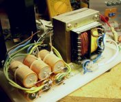
Overview of this Class A amplifier setup.
To the left: 2 standing heatsinks. Each one with one Big TO-3 power transistor.
Middle: for V+ 0V V-, 2x3 of 4700uF 63V (makes 2 x 14100uF )
Right: One 26VAC 100VA E-Type trafo.
I did open the secondary winding and made it 2x13VAC.
Was terribly hard & dificult work to do ....
You can see the thick dark-red wire of this secondary.
lineup
Attachments
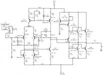
I decided to go ahead and build another of these circuits to play with, the only version i still had are the full ccs version. Although i did include the ccs for the output stage the vas is still just the simple version. It started up and works nicely. So here is what i built, it should work with your transistors with no changes other than the size of the pot needed to adjust offset. Much less hum than i expected using only a 18000uF after the diodes no filters.
Attachments
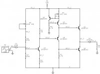
DoomPixie, I suspect that bootstrap is the cause of nearly all your hum. Since there is such a small resistance to the rail before the capacitor it is injecting pretty much all the ripple on the rail straight to the output. Using the ccs on just the output section and basically no filtering in the ps the hum is quite bearable in my circuit. I also tweaked around a little bit on the circuit. Reffering to the schema in post 117, changed r2 to 100 ohm, changed r6 to 220k. I had forgotten how good this circuit sounds,campared to the one using ccs loaded vas this one sounds a bit better.
I must say adding the CCS to the output does make this amplifier a LOT easier to get working right.. I'm going to build the ccs version tommorow and see how it works in real life
A bit off topic but does anyone know the specs and how to wire the transformers that are in the APC smart UPS 700? I just got given 4 of these that someone puleld out of a skip, all work fine but have dead batteries, have replaced the batteries in two of them and put them into service here but am stripping the other two down for parts, Was thinking mabey they could be usefull for something, They weight a LOT and seem to be very well made transformers....
Owen
- Status
- This old topic is closed. If you want to reopen this topic, contact a moderator using the "Report Post" button.
- Home
- Amplifiers
- Solid State
- My simple class a approach