Member
Joined 2009
Paid Member
Re: I was fan too.
http://www.youtube.com/watch?v=aIvD0sAyk5g
destroyer X said:A pitty.... a shame i have not the channel into my Satelite TV.
http://www.youtube.com/watch?v=aIvD0sAyk5g
 off topic post deleted
This is by no means a criticism but (I think) I have noticed a lovely open midrange which brings out the sound of vocals and other instruments in the upper midrange.
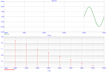
Firstly is the aksa frequency response flat?
And is what I've noticed the result of distortion which has deliberately been added?
Would it be fair to say that the aksa sound is also similar to the vinyl format or not?
Firstly is the aksa frequency response flat?
And is what I've noticed the result of distortion which has deliberately been added?
Would it be fair to say that the aksa sound is also similar to the vinyl format or not?
IIRC Hugh has added a slight amount of H2 which comes from his work with tubes. Have a look at the AKSA details on his site (or the instructions) and there is a description of the sonics and part of that is to add some tube qualities.
AFAIK the response is flat as I haven't noticed variations against scores of other amps I've tried.
AFAIK the response is flat as I haven't noticed variations against scores of other amps I've tried.
Member
Joined 2009
Paid Member
Happy engines
I also note (having watched from the sidelines since the beginning) that the AKSAs seem to make it into the secondary market very, very rarely.
IE the customers are happy with the ending. And that is the main thing.
AKSA said:Yes, and the fact it engages.....
However, the story has a happy ending and that is the main thing.
Cheers,
Hugh
I also note (having watched from the sidelines since the beginning) that the AKSAs seem to make it into the secondary market very, very rarely.
IE the customers are happy with the ending. And that is the main thing.
aksa 55 etc
Just because an amplifier cct does not have a CC or Current mirror, does not invalidate its performance..Consider this scenario, even if you match very closely a differential I/P pair you will still have a common mode difference
which in the typical diff pair is complicated because it is across two different
transistors and the assumption is that what is fed back via the feedback loop
is identical to what is fed into its I/P but for the phase difference, unfortunately because the loudspeaker produces an impedance variation,
which in turn is also fed back to the diff pair albeit in reduced amplitude,
it is assumed that this is all somehow balanced out alas this is not quite true
because the impedance plot of the loudspeaker represents a changing phase
which is fed to the feedback side of the diff pair, now the diff pair has to cope with this factor plus the common mode errors, now in the Bailey cct
the I/P and the feedback is applied to a single transistor, so there is no common mode error, the control is also instant being in the same electron stream and this may account for some of the perceived accuracy of this topography, Dr Bailey who also designed the Bailey line transmission line back in the 60's, originally conceived this amp as a 30watt job using rather slow transistors by todays standards but after resolving a bad case of early effect in the main driver transistor was eventually able to produce a square wave at 50khz with little error he was using an RCA 40362 in the driver transistor for low cob and small early effect.. Of course there are better devices today..You can have a good amp with a CCS and current mirror if you remember to design for very high damping factors as this will reduce the
amount of loudspeaker impedance variations getting back into the feedback loop.Meridian did much work on this reflected impedance over 25 years ago
to deal with this type of problem..Its all well known..and it may be why some people like amps with no overall neg feedback..its all about proper design..Also J.Linsley Hood's class A amps of 15watts to 30watts also used a single I/P transistor and it was well thought of for its clarity..
In its day the Bailey amp was highly regarded although it was a class B,
despite which its distortion at full power and throughout the freq range was well under 0.1% regards
Humble
Sorry to butt in, still forgiven!!Hi Forr,
With all due respect, the thread topic asks for "Listening impressions" For some reason I get the impression that you have not listened to one. Do you have something against Hugh?
Please, let's not muddy the waters. Many of us are curious how this amp actually sounds in comparison to some of the other popular DIY amps.
Blessings, Terry
Just because an amplifier cct does not have a CC or Current mirror, does not invalidate its performance..Consider this scenario, even if you match very closely a differential I/P pair you will still have a common mode difference
which in the typical diff pair is complicated because it is across two different
transistors and the assumption is that what is fed back via the feedback loop
is identical to what is fed into its I/P but for the phase difference, unfortunately because the loudspeaker produces an impedance variation,
which in turn is also fed back to the diff pair albeit in reduced amplitude,
it is assumed that this is all somehow balanced out alas this is not quite true
because the impedance plot of the loudspeaker represents a changing phase
which is fed to the feedback side of the diff pair, now the diff pair has to cope with this factor plus the common mode errors, now in the Bailey cct
the I/P and the feedback is applied to a single transistor, so there is no common mode error, the control is also instant being in the same electron stream and this may account for some of the perceived accuracy of this topography, Dr Bailey who also designed the Bailey line transmission line back in the 60's, originally conceived this amp as a 30watt job using rather slow transistors by todays standards but after resolving a bad case of early effect in the main driver transistor was eventually able to produce a square wave at 50khz with little error he was using an RCA 40362 in the driver transistor for low cob and small early effect.. Of course there are better devices today..You can have a good amp with a CCS and current mirror if you remember to design for very high damping factors as this will reduce the
amount of loudspeaker impedance variations getting back into the feedback loop.Meridian did much work on this reflected impedance over 25 years ago
to deal with this type of problem..Its all well known..and it may be why some people like amps with no overall neg feedback..its all about proper design..Also J.Linsley Hood's class A amps of 15watts to 30watts also used a single I/P transistor and it was well thought of for its clarity..
In its day the Bailey amp was highly regarded although it was a class B,
despite which its distortion at full power and throughout the freq range was well under 0.1% regards
Humble
- Status
- This old topic is closed. If you want to reopen this topic, contact a moderator using the "Report Post" button.
- Home
- Amplifiers
- Solid State
- AKSA 55, 100 - Listening impressions