Hi, again.
Sorry it is old thread. But it is fun to play with Candy's stuff. Because this EC is not a bad one.
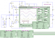
Now I am combining Bumps with Candy's. The result is Candy's EC with frequency independent THD figures, almost flat at all freq.
Other result is much more stable than my complex bumps.
The other things again is Halcro has good reputation in sound quality until this day and survive from many threat.
The other of other is bad. It is patented, by Mr. Candy.
Here it is:
Sorry it is old thread. But it is fun to play with Candy's stuff. Because this EC is not a bad one.
Now I am combining Bumps with Candy's. The result is Candy's EC with frequency independent THD figures, almost flat at all freq.
Other result is much more stable than my complex bumps.
The other things again is Halcro has good reputation in sound quality until this day and survive from many threat.
The other of other is bad. It is patented, by Mr. Candy.
Here it is:
Attachments
sorry, what is "Bumps"??
Got a reference?
Also it is hard to see your schematics on some of your images.
Have you looked at the effects of bias point?
I'd bet that the one(s) with the distortion products that look more or less sinusoidal or smooth will actually sound best, regardless of absolute distortion levels. Just a guess.
_-_-bear
Hi,
@bear
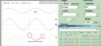
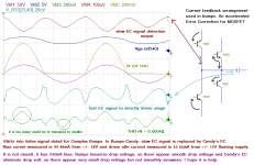
Bumps is just a current feedback arrangement, I like to call it Bumping Feedback because it has two collector and two emitter connected in single node together with capacitor leg as additional output (five branch node).
Crossover distortion normally increases by load, also it just micro volts and output filter is not present. When output filter applied it will smaller.
Umm...Don't no, Is it ok showing complete value of patented schematic. also it isn't real values, just coming from tweaking.
@Bonsai
It is already very small, and halcro added more feedback(GNFB) to reduce it.
@Jcx
GNFB could reduce distortion and normalize HF components and output filter could reduce HF components, but good EC will much help. No doubt class A has no crossover distortion.
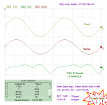
This one is 8ohm load at 10kHz Bumps-Candy's EC, crossover distortion is much smaller. (still no output filter). I am still tweaking it, it is fun.
@bear
Bumps is just a current feedback arrangement, I like to call it Bumping Feedback because it has two collector and two emitter connected in single node together with capacitor leg as additional output (five branch node).
Crossover distortion normally increases by load, also it just micro volts and output filter is not present. When output filter applied it will smaller.
Umm...Don't no, Is it ok showing complete value of patented schematic
. also it isn't real values, just coming from tweaking.@Bonsai
It is already very small, and halcro added more feedback(GNFB) to reduce it.
@Jcx
GNFB could reduce distortion and normalize HF components and output filter could reduce HF components, but good EC will much help. No doubt class A has no crossover distortion.
This one is 8ohm load at 10kHz Bumps-Candy's EC, crossover distortion is much smaller. (still no output filter). I am still tweaking it, it is fun.
Attachments
Last edited:
Halcro's patents can be copied, simmed - everything about them is public domain
even as currently active patents they are free for discussion/education - thats why they are published
you just can't "make, use, sell" amp's with the circuits covered by the patent's exact claims - at the risk of getting sued by Halcro
and like most patents there is plenty of room for questioning the scope, "originality" of the claims - particularly Halcro's "kitchen sink" schematics contain much "piror art" - even in the core error correction ideas
Last edited:
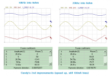
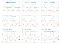
This is the first Candy's EC improvements, but only tiny differences. May be something wrong.
@bear
I am just limit bias output by 100mA. Surely with 250mA they are very good, but it doesn't showing the special use of good EC.
Sorry, no values. I don't want to have problem with them, for complete values, use PM. Can't "make, use, sell". Just don't want supporting "make".
@bear
I am just limit bias output by 100mA. Surely with 250mA they are very good, but it doesn't showing the special use of good EC.
Sorry, no values. I don't want to have problem with them, for complete values, use PM. Can't "make, use, sell". Just don't want supporting "make".
Attachments
Last edited:
without values no one can tell what you're really doing - for instance the circuit you're calling "Bumps" is biased at 5 A according to its own thread - why I was saying you're making totally unfair comparison – need to “open” your work to inspection
its unlikely that Halcro’s patent drawings are all that close to his actual amplifier circuits, even so it would be legal to publish the exact reverse engineered circuits of Halcro amps - I doubt many would really want to clone them given the Stereophile measurements or the availability of Self, Cordell book's circuits performance at considerably lower complexity
its unlikely that Halcro’s patent drawings are all that close to his actual amplifier circuits, even so it would be legal to publish the exact reverse engineered circuits of Halcro amps - I doubt many would really want to clone them given the Stereophile measurements or the availability of Self, Cordell book's circuits performance at considerably lower complexity
comparing similar output device currrent bias really is better - Class A output bias eliminates most of the higher order components that EC is really good for
Yes, I agree
@jcx
Don't worry. I am a fair guy, and I am lawfull person, I usually stop at red traffict light too, when everyone just go.
I still trying to improve Candy's as well to reach its best performance. According to the "Amplifier Imprevement" patent, this halcro amp become complex with mosfet buffers/drivers and its dynamic biasing circuit.
Attachments
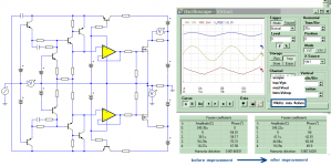
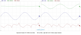
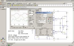
This one is differences between using output inductor and without it. Big enough, 2uH. Seems that the output inductor is help for global negative feedback application, and not for crossover distortions.
Top trace is drop voltage:
Top trace is drop voltage:
Attachments
Ok, this is the last things to do to speed up this error correction, Like I said before, it is good EC, Candy's is not comparable with previous hawksford's.
Reaching 0.0002% THD+N, with: easy tweak, easy built, no need component precision and matcing, simpler and so... baadd.... He got it patented.
Reaching 0.0002% THD+N, with: easy tweak, easy built, no need component precision and matcing, simpler and so... baadd.... He got it patented.
Attachments
Sometimes some members complain when replying to a thread that's been a few years old (not only by me). Thus the most members start a new thread on the same subject or do not at all to this. Until this day I haven't understand that.Hi, again.
Sorry it is old thread. But it is fun to play with Candy's stuff. Because this EC is not a bad one.
Now I am combining Bumps with Candy's. The result is Candy's EC with frequency independent THD figures, almost flat at all freq.
Other result is much more stable than my complex bumps.
The other things again is Halcro has good reputation in sound quality until this day and survive from many threat.
The other of other is bad. It is patented, by Mr. Candy.
Here it is:
Therefore thank you for using this old thread and your informations so as your simulation results.
I will deal with it in the next weeks (unfortunately, the Christmas holidays fall exactly in the days of the weekend this year).
Last edited:
Hi, tief,
Thanks a lot.
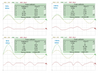
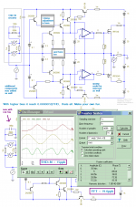
Now the 4th improvements. Now the target is linearity. Reaching lowest THD I ever simulated 0.000027% or 0.27ppm or 270ppb. That is close to their claim to be achieved distortion.
The output stage is still 1pair IRF540/9540 with 100mA bias. All other transistors is 2n3904/06 with fast opamp as mosfet driver as picture at previous post.
So halcro amp must have very small amount of global negative feedback, and GNFB may just applied to refine its sound quality, instead of THD figures.
improvenebt 4: 0.000027%THD:
Thanks a lot.
Now the 4th improvements. Now the target is linearity. Reaching lowest THD I ever simulated 0.000027% or 0.27ppm or 270ppb. That is close to their claim to be achieved distortion.
The output stage is still 1pair IRF540/9540 with 100mA bias. All other transistors is 2n3904/06 with fast opamp as mosfet driver as picture at previous post.
So halcro amp must have very small amount of global negative feedback, and GNFB may just applied to refine its sound quality, instead of THD figures.
improvenebt 4: 0.000027%THD:
Attachments
This the last things, yes schematic. This is what I currently simulate for those results.
The next is VAS stages, but it is seem useles, i have already similar things. and many other also has similar too, and simulate it in other threads.
The next is VAS stages, but it is seem useles, i have already similar things. and many other also has similar too, and simulate it in other threads.
Attachments
Last edited:
- Status
- This old topic is closed. If you want to reopen this topic, contact a moderator using the "Report Post" button.
- Home
- Amplifiers
- Solid State
- halcro amplifier