Re: Re: Hi jorge..
Be my guest!") GP.
GP.
peranders said:Circlotron's class A amp is surely patentable!
Be my guest!
GP.Re: Hi jorge..
If they do, the Patent Office has made an error. Disclosure is a disqualifier for patent applications.mikek said:You are absolutely correct.....amazing how people can get away with patenting someone elses idea that has been public domain for near 20 years...
Another choice for low distortion
I was searching for like technology on the Internet and found this link interesting. It appears to be a front-end module that is capable of driving output stages and produces very low distortion. Is feedback scheme appears to be some what similar to what the Halcro uses. The module can drive output stages ranging from 50 to 1000 watts.
The link below gives a brief description and also Audio Precision distortion and intermod curves for a typical amplifier that uses this module. The low distortion figures are quite impressive.
http://www.profusionplc.com/static/images/data sheets/SE2090EV1.pdf
Has anyone looked at this before? In any case I figured there might be some interest in this module.
John Fassotte
Alaskan Audio
Looking at the circuit, it is clear that Halcro values low
THD figures and is pulling out all the stops to get them.
Whether this will result in commercial success is unclear,
as previous efforts like this have not, most notably the
Nakamichi amplifiers which offered 7 parts per million
distortion.
At Threshold, they built a version of the Hawksford/Cordell
circuit for the Forte IGBT amplifier as I was leaving. It got
lower distortion, but didn't sound particularly good IMHO.
If you look at the bias circuit for the Threshold "dynamic
bias" products, you'll see the same arrangement, where
complementary bias devices look at the output node through
diodes and adjust their Vbe amplification to compensate
for the varying voltage drops in the follower output stage.
As I recall, you can see this on the patent page of
www.passlabs.com/images/articles/pat_3995.jpg
Distortion levels versus the amount of signal modificationsig
I have over the years also valued low distortion figures, but I have also become more educated on the subject and have found that the tremendous amounts of negative feedback required to reduce distortion to almost immeasurable levels is not beneficial to sound quality. Reasonable levels of negative feedback are however just fine to control both distortion and output impedance. I feel that distortion levels lower than .06 percent normal listening levels and at mid frequencies have little if any benefit. This would represent a distortion level of perhaps –75DB give or take a little. This level of distortion can be obtained with reasonable levels of negative feedback
Many amplifiers use of current mirrors and to some extend constant current sources in low levels stages. In many cases these appear to have only one primary purpose, which is to increase stage gain. This increased gain directly relates to the amount of negative feedback required to reduce the stage gain back to a normal value. If a current mirror increases stage gain by 40 or 60 DB then 40 or 60 DB of negative feedback is required to bring the stage gain back to normal. The increased amount of negative feedback that needs to be applied to bring the stage gain back to normal also decreases the apparent distortion to extremely low levels. I don’t believe that this is beneficial in the terms of sound quality
There are of course other reasons for using current sources and current mirrors, but for the most part they can increase stage gain, thus increasing negative feedback, which makes the stage appear to be more linear than it actually is. Thus in circuits that report extremely low distortion figures you will likely find terrific amounts of negative feedback used of some kind. Add more local feedback, call it error correction if you like, around a source follower output stage and distortion will also reduce drastically since we are modifying the linearity of its input signal to something that is curved to make the output stage happy with the error correction. All in all a lot of signal modification takes place in a amplifier with very low distortion figures. The reason for this is of course is that active devices we have to use are really not all that linear. It takes a lot of signal modification through the use of some kind of feedback to go from an average of -40DB distortion levels of most active devices down to the –120 or –130DB level.
Low distortion figures do make good marketing tool to sell a new product to persons who are bored with the equipment they already have. All of us would like to have an amplifier that that would appear not to add any coloration to the signal it is processing. It is to bad that in real life this does not happen. The bending and shaping of the signal being processed with or without feedback will just not allow it.
John Fassotte
Alaskan Audio
Global Negative Feedback
I would like to affirm John's observations, and add a few of my own.
I am relatively new to amp design, around 8 years, so my experience is not so great, but certainly I roundly agree.
I'd like to add a few points to confirm John's findings.
1. Excessive negative feedback does indeed bring back single tone distortion measurements, but creates a myriad of high-order, subliminal, and often odd-order artefacts which are highly objectionable to the human ear. For example (I read this somewhere years ago, but cannot remember the source!): A trumpet played hard and loud has an additional 0.05% of H5, H7 and H9 over a quietly played trumpet, yet if adjusted for amplitude and heard from some distance, sounds very different despite a H2/H3/H4 spectral composition essentially the same. This very clearly draws attention to the spectral distribution of the distortion, something not given much credence in anything but tube circles.
2. Because of the near infinite impedance presented to a voltage amplifying device by a current source, tubes and SS, the device is thus able to offer its full voltage amplification. In a tube, this is mu, in a transistor, it is the ratio of the collector to the emitter impedance, with the influence of beta thrown in, and is typically 60dB. The stage gain of a transistor with a near-infinite collector load is very different to a finite load. For a given overall gain, this naturally increases feedback factor, which, beyond a certain point as John points out, is undesirable for sound quality.
3. A current mirror or source is also very fast, and furthermore makes the gain of the stage extremely sensitive to impedance changes in the following, driven stage. If the output stage is push pull, the variation in impedance of this load with signal is quite radical, yet this is rarely discussed in light of the uniformly high impedance presented by the current source supplying current to the amplifying device. Global negative feedback is expected to 'fix' this problem, and yet the impedance changes, like a tube grid moving into positive bias, is quite sharp at the crossover transition.
4. We need to give more attention to the voltage amplifying device itself, since we need to pull its open loop gain back to below unity at the pole frequency by adding lag compensation across its input/output (base/collector). Rather more lag compensation is required with a current mirror load; this is because we must pull the OLG back to below unity by the pole frequency to avoid instability. Because the usual 6dB/octave single pole compensation is contending with more OLG to begin with, this compensation is more savage than it otherwise might be. Lag compensation is bad because it slows the amplifier and traditionally the voltage amplifier is the slowest stage of a global nfb amp. The amp must be nimble. If it were possible to pull back OLG by using a finite load which rapidly increased its loading at higher frequencies for other, unrelated reasons, then such savage compensation might not be necessary.
5. In closing, I would say that all amplifiers sound worse as one increases the lag compensation. Too much is leaden and flat; too little is fuzzy - and risky for tweeters - as the amp lapses into short term instability on transients. The trick is to arrange it so that this compensation is both optimal and minimal - a tall order, but one with sonic rewards.
Cheers,
Hugh R. Dean
www.aksaonline.com
Re: Global Negative Feedback
AKSA said:I would like to affirm John's observations, and add a few of my
------------------------------------------------------------------------------------
1. Excessive negative feedback does indeed bring back single tone distortion measurements, but creates a myriad of high-order, subliminal, and often odd-order artefacts which are highly objectionable to the human ear. For example (I read this somewhere years ago, but cannot remember the source!): A trumpet played hard and loud has an additional 0.05% of H5, H7 and H9 over a quietly played trumpet, yet if adjusted for amplitude and heard from some distance, sounds very different despite a H2/H3/H4 spectral composition essentially the same. This very clearly draws attention to the spectral distribution of the distortion, something not given much credence in anything but tube circles.
2. Because of the near infinite impedance presented to a voltage amplifying device by a current source, tubes and SS, the device is thus able to offer its full voltage amplification. In a tube, this is mu, in a transistor, it is the ratio of the collector to the emitter impedance, with the influence of beta thrown in, and is typically 60dB. The stage gain of a transistor with a near-infinite collector load is very different to a finite load. For a given overall gain, this naturally increases feedback factor, which, beyond a certain point as John points out, is undesirable for sound quality.
3. A current mirror or source is also very fast, and furthermore makes the gain of the stage extremely sensitive to impedance changes in the following, driven stage. If the output stage is push pull, the variation in impedance of this load with signal is quite radical, yet this is rarely discussed in light of the uniformly high impedance presented by the current source supplying current to the amplifying device. Global negative feedback is expected to 'fix' this problem, and yet the impedance changes, like a tube grid moving into positive bias, is quite sharp at the crossover transition.
4. We need to give more attention to the voltage amplifying device itself, since we need to pull its open loop gain back to below unity at the pole frequency by adding lag compensation across its input/output (base/collector). Rather more lag compensation is required with a current mirror load; this is because we must pull the OLG back to below unity by the pole frequency to avoid instability. Because the usual 6dB/octave single pole compensation is contending with more OLG to begin with, this compensation is more savage than it otherwise might be. Lag compensation is bad because it slows the amplifier and traditionally the voltage amplifier is the slowest stage of a global nfb amp. The amp must be nimble. If it were possible to pull back OLG by using a finite load which rapidly increased its loading at higher frequencies for other, unrelated reasons, then such savage compensation might not be necessary.
5. In closing, I would say that all amplifiers sound worse as one increases the lag compensation. Too much is leaden and flat; too little is fuzzy - and risky for tweeters - as the amp lapses into short term instability on transients. The trick is to arrange it so that this compensation is both optimal and minimal - a tall order, but one with sonic rewards.
------------------------------------------------------------------------------------
Hugh has made some importent observattions regarding Audio Amp Design. I for the most part agree with the Above statments and totaly agree with respect to Lag Compensation. Years ago when i would do Mod's on Audio Amps,One of the first thing to get removed or Reduced was the Phase lag Network. this greatly improved the Midrange and High End by reducing the harshness and glare of the Amp. To maintain Stability I would then reduce the Openloop gain by eather using Emmiter resistors on the Input stage diff Amp and or Puting a load resistor on the Output of the Second Vas stage. Sometimes using a higher value of emmiter resistor than was used on this stage was done to futher reduce the Open Loop gain if needed. The Load resistor would also somewhat offset the Dramatic impedance changes seen by the Second vas stage from the Output Stages input Impedance Changes. The result was alot Cleaner and more stable Amp.
When I did my own Amp designs i would then not fall into the trap of using all sorts of Compensation methods to stabilize the Amp Circuit. Phase Lead compensation is also bad as it slowes the Amp down I like to have stability come naturaly by using the exsisting capacitence of the devices and selecting the open loop gain so as the have the Unity gain crossing frequency happen prior to the first pole. This will produce higher THD numbers and in DC coupled designs require care with DC offset, however correction methods are available to take care of this.
I also like to have the open loop gain be constant across the Audio bandwidth as this produces a Consistent THD number with frequency and not have the rising THD vs Frequency typical of Circuits using high open loop gain and limited open loop bandwidth.
Current sources & Mirrors can be quite usefull if properly used and used in the right places. using a current source to supply current to the Emmiter's of the Input Diff amp is a good thing as it improves both the comon mode as well as the Power supply rejection ratio of the Circuit. Current Mirror's used on a folded cascode Voltage gain stage can also give good results, however on the more conventional cascode or comon Emmitter stage thay as Hugh pointed out can create problems unless the operating current is set so high so as to be able to drive the Output stage's non linear impedance at it's worst case.
Using Feedback around just the output stages is not IMHO a good thing as it reduces the Stability and speed of the output stage and this stage must by nature be alot faster than the Vas stages to avoid instability.
Re: Another choice for low distortion
Hi John,
the distortion figures might be impressive, but for the normal customer, who is listening in the of 100mW to 500mW at home, the above document shows clearly that at these levels, the distortion figures and the noise is a lot higher. The problem is that low distortion occurs only when the output power is high, but then the listening level is very high too, and also the ear's intrinsic distortion.
So it is absolutely useless designing a power amp having 0.1% distortion at 100mW and 0.0001% distortion at 100W. It should be better the other way round.
regards,
Hartmut
alaskanaudio said:
The link below gives a brief description and also Audio Precision distortion and intermod curves for a typical amplifier that uses this module. The low distortion figures are quite impressive.
http://www.profusionplc.com/static/images/data sheets/SE2090EV1.pdf
John Fassotte
Alaskan Audio
Hi John,
the distortion figures might be impressive, but for the normal customer, who is listening in the of 100mW to 500mW at home, the above document shows clearly that at these levels, the distortion figures and the noise is a lot higher. The problem is that low distortion occurs only when the output power is high, but then the listening level is very high too, and also the ear's intrinsic distortion.
So it is absolutely useless designing a power amp having 0.1% distortion at 100mW and 0.0001% distortion at 100W. It should be better the other way round.
regards,
Hartmut
Great thread so far
Nelson, AKSA, Alakanaudio, ppl, ...
great ! I feel at home, you made the same experiences as I. In the 80ies and early 90ies I tried to solve the power amplifier design problem by using all the magic schematic tricks, cascodes, folded cascodes, floating cascodes, current mirrors, complementary feedback output darlingtons ... well without success. While sounding neutral in tonality, my power amps designed so failed to deliver lookthrough clarity or even musical insight.
As with Naim amps or AKSA amps, the secrets are not in the plain schematic, but in the way, the schematic is filled with life by choosing operating points, resistor values, transistor brands, high frequency poles ...
So no textbook reading helps to become a competent designer, and all my some metres of amplifier design books and articles (I still collect them when they seem useful, though) are nearly untouched the last years.
Funnily, my father had a power amp made by a transistor Guru 20 years ago, which sounded great, and, when it eventually blew the power supply, I drew the schematic, and surprise surprise it was about 90% of the AKSA.
regards,
Hartmut
hifidaddy;
Yes i also think that God is in the Details. Also I have been investigating the Rising THD at low power levels and like you i think that Noise and Crossover distortions may be the reason for this. The Best i have been able to get is somewhat constant THD down to 25 Mw, But would like to improve upon this as this is the range that Detail's of the Music are in. any thoughts on this would be interesting.
Yes i also think that God is in the Details. Also I have been investigating the Rising THD at low power levels and like you i think that Noise and Crossover distortions may be the reason for this. The Best i have been able to get is somewhat constant THD down to 25 Mw, But would like to improve upon this as this is the range that Detail's of the Music are in. any thoughts on this would be interesting.
Low level distortion
I would like to give my thoughts on low-level distortion in power amplifiers. Most power amplifiers are fairly noisy beasts when we compare them to other items in the amplification chain. The noise floor in a power amplifier is going to be the most limiting factor in reproducing low-level signals passing through it. In order for a amplifier not to be influenced by its own noise to any great extend during its amplification process the noise floor must be well below the minimum signal we wish to recover cleanly at the amplifiers output. If my fast calculations are correct 25mw of signal equals roughly 79mv RMS across 4 ohms. Thus to obtain a signal to noise plus distortion figure of better than 40DB (1 percent) the output noise of the amplifier itself cannot exceed .79mv RMS. Most power amplifiers will have some trouble reaching that goal. To determine the actual cause of low level signal distortion in a power amplifier some test equipment such as a FFT analyzer would come in handy for looking at noise floor and distortion products at low signal levels. I rather suspect that this will show that the noise floor most power amplifiers will be the primary limiting factor in low-level distortion.
It should be remembered that the small signals generally ride on top of a much larger waveform, and that the nuances are thus part of a much larger picture. They are truly not alone at anytime in the signal stream of a amplifier. If the main program material is operating at very low levels then the nuances, which are of much lower levels are likely being pumped in and out of the noise floor.
The noise floor of a amplifier is stated in many different ways in specification sheets. Some will state the actual noise level present at the output of a amplifier with both the input ant output terminated with proper value loads. Others refer the noise floor to a 1 watt output level into a specific load impedance, while others refer it to the full output power level of the amplifier.
If I’m wrong in any of my calculations please feel free to correct me.
John Fassotte
Alaskan Audio
alaskanaudio>
Thanks alot for your Input. Your calculations seem Right to me as in the Amp in question i get just under 1Mv unloaded at the Output. This is a 300W @ 8 Ohm Pwr amp Based somwhat upon the leach and Sumo Designs. the unloaded RMS output Voltage just prior to Clipping is 72 Volts. Most of my test Equipment is Old Analog Stuff like an Old Leader THD anili. using a Built in Meter and Scope. My Other Scop is an old Techtronics 434 storage Scope of only 20 MHz. and Circa 1971. FFT is not available to me at this time. so you may be Right Noise may be the Cause. Thank you alot for your time.
Thanks alot for your Input. Your calculations seem Right to me as in the Amp in question i get just under 1Mv unloaded at the Output. This is a 300W @ 8 Ohm Pwr amp Based somwhat upon the leach and Sumo Designs. the unloaded RMS output Voltage just prior to Clipping is 72 Volts. Most of my test Equipment is Old Analog Stuff like an Old Leader THD anili. using a Built in Meter and Scope. My Other Scop is an old Techtronics 434 storage Scope of only 20 MHz. and Circa 1971. FFT is not available to me at this time. so you may be Right Noise may be the Cause. Thank you alot for your time.
Cordell circuit
I built up an exact copy of the Cordell paper circuit years ago, and some variations with improved current mirrors and front end cascode, but without the so called error correction circuit around the output stage. And the IR FET based output stage was replaced with a CPF type stage using Magnetec/Semelab lateral mosfets. The latter version measured almost as good as the Cordell circuit, but IMO sounded quite a bit better; probably due to the multiple output devices and lower inherent output impedance - maybe the reduced loop feedback, too.
A chip that uses a similar configuration to the Cordell error correction around the output stage is the LT1166. Both the Cordell circuit and the LT chip have greatly diminishing effects above 20 kHz, and this is a liability for a high feedback design, in my opinion.
Best regards,
Jon
p.s. repeating a question I asked months ago, has anyone
(successfully or not) built the Cordell amp design that
used the Hawksford circuit? It's far less complex than
the Halcro and has some amazing ("objective") specs
of its own. (but what does it sound like?)
I built up an exact copy of the Cordell paper circuit years ago, and some variations with improved current mirrors and front end cascode, but without the so called error correction circuit around the output stage. And the IR FET based output stage was replaced with a CPF type stage using Magnetec/Semelab lateral mosfets. The latter version measured almost as good as the Cordell circuit, but IMO sounded quite a bit better; probably due to the multiple output devices and lower inherent output impedance - maybe the reduced loop feedback, too.
A chip that uses a similar configuration to the Cordell error correction around the output stage is the LT1166. Both the Cordell circuit and the LT chip have greatly diminishing effects above 20 kHz, and this is a liability for a high feedback design, in my opinion.
Best regards,
Jon
I'll have to scan it and upload it to my posting site; I don't have it in my current CAD software (Protel). Because I'm leaving for Germany on business in a couple of days it may be the week after next before I can post it, but I will get to it. With luck, perhaps before I go!
Regards,
Jon
Regards,
Jon
Cordell Circuits
Please see below.
Best regards,
Jon
Please see below.
Best regards,
Jon
An externally hosted image should be here but it was not working when we last tested it.
An externally hosted image should be here but it was not working when we last tested it.
Jon,
Could yu post the Cordell circuit?
Thanks,
Jam
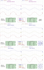
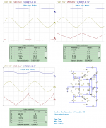
I am doing some comparison, take a look.
Also with my bumps style error correction result.
I've tried to tune candy's EC, but ended for just 0.001%THD both candy's and cordell's not as good as my bumps feedback. May be my models not very good or something, because Halcro says reaching ppm scale or less than 0.001%THD at local output stages assuming they using 20dB global NFB.
Attachments
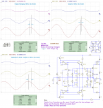
This is another results, and also showing my improved bumps feedback results.
Bumps EC is originally designed for mosfets to deal with non linearity and gate charging effect, unlike the hawksford's based that designed first for BJT's in very long time ago.
Bumps EC is originally designed for mosfets to deal with non linearity and gate charging effect, unlike the hawksford's based that designed first for BJT's in very long time ago.
Attachments
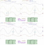
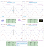
My,, I forgot to add bootstrap on candy's EC. Here bootstrap added with different configuration, this configuration may the correct one because that VR is adjusted to eliminate drop voltage instead of linearize it. Now reach 0.0004% THD.
Anyway, lack of bass isn't caused by current limiting. Also they are not any same between Candy's and Cordell's EC. They have very different each other.
Anyway, lack of bass isn't caused by current limiting. Also they are not any same between Candy's and Cordell's EC. They have very different each other.
Attachments
- Status
- This old topic is closed. If you want to reopen this topic, contact a moderator using the "Report Post" button.
- Home
- Amplifiers
- Solid State
- halcro amplifier