MikeB said:Hi !
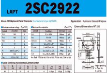
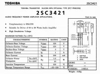
Reichelt has them both, the 2sa1358 and 2sc3421.
Mike
Yes - they have a minimum order and this is not very good but I think that it will be o.k.
thanks for the info - and best regards

Hi Sunrise,
It is possible to measure base-emitter junction forward potential on many multimeters as well as gain, so it might be worthwhile to try matching a pair. Though if you use same manufacture, batch and gain range you could be okay without checking.
I have not had more than 15mV offset with random selection at different times. Once only 2mV.
If you have an offset that slowly drifts then that generally means that one of the input pair is receiving more direct radiation from the driver/output stage than the other, I once had this and cured it by inserting a heat insulating screen.
Does so small an offset have audible impact ?
20mV / 4 ohms = +/-2.5mA output stage imbalance, and as Carlos says, that is a near constant 100uW at the loudspeaker.
I think any of us would change the input devices if we measured 20mV though !
I buy my genuine Toshiba transistors from Cricklewood Electronics in London. They offer A1+ personal service via telephone for credit card orders, and charge minimum for postage or your choice of delivery. The also list Sankens plus lots of others.
Find them via
www.cricklewoodelectronics.com
No minimum order.
I can normally find semiconductor spec sheets via an Internet search with device number and the word data. Always enter the NPN number of complementary pair types.
Cheers .......... Graham.
Friends are sending messages asking for 25W GEM
Here is the link:
http://www.diyaudio.com/forums/showthread.php?postid=467170#post467170
The schematic is attached.
regards,
Carlos
Here is the link:
http://www.diyaudio.com/forums/showthread.php?postid=467170#post467170
The schematic is attached.
regards,
Carlos
Attachments
mr. maynard, I have much to learn..... thank You for the opportunity to learn from the best (mr. MikeB - please count Yourself also here, and some other guys to - many smart guys here....)
that link is good - lots of nice stuff.
thanks - i think that will do it..")
mr. Carlos - You are really something - I have found those datasheets also - but Your need to help is remarkable - thanks againnn
happy diy
best regards
that link is good - lots of nice stuff.
thanks - i think that will do it..
mr. Carlos - You are really something - I have found those datasheets also - but Your need to help is remarkable - thanks againnn
happy diy
best regards
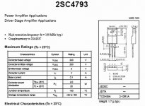
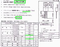
This one has not so good speed, but can do a reasonable work as drivers and output.
If you decide to use this one, i suggest you to assemble at least three units in parallell, having 2,2 ohms stop resistor to each base and 0.33 ohms resistors to each emitter.
This way, you will produce a nice power transistor, and having around 150 of gain, 18 amperes for 3 units, and around 200 watts heat dissipation.
The problem is that will work fine till 3 Megahertz, but, when using it to low voltage output amplifiers, the slew rate will not create too much problem...as to go from zero to 20 volts will not delay too much.
The advantage is the price and because is easy to find.
Have to consider the increase of capacitances when parallelling those units.
I made one 25W GEM with those transistors and result very nice, i tried also AKSA with them, and worked nice too.
So good as Sankens?...NO NO NO!
But you will buy three for a dollar...very interesting 200 watts for a dollar!
regards,
Carlos
Attachments
Sunrise, i have learned a lot in this forum, this way, i feel myself with the ...
obligation to help the ones that are entering the forum, and in special the ones that are starting with the hobbie.
I had my Sargeant in the Army, that teached me a lot of important things, including how to smoke a good pipe.
Now is time to inform things that i could learn reading, hearing, doing and feeling related audio.
I thank you very much...but really, this is some obligation we must have, as someone had helped us some day in the past.
I will be out of Internet for three days, because of upgrades that will be made in my Telephon line System.... the company will install very high speed system now.... will go to near 1 Gigahertz of data transmission speed...download will jump from 26K to 100K..
So...i will disappear for some time, and will not answer mails.
regards,
Carlos
JLH Class A
Hi Carlos
Thank you for the answer.
I understand that the GEM amplifier is better than JLH.
Can you explain why i will have problems with GEM because of high efficients speakers?
Do you think that the 1969 JLH is better than the new one? (my second version use split power supply, no electrolytic feedback cap at the emitter input cap and MJ15003 output transistors)
My own impression is that the 1969 as something that miss in the new one.(same output transistors)
Carlos, you are a great guy on forums with a sense of humor that make this hobby very pleasant!
Will miss you these 3 days!
Thanks again and Have a good day
Hi Graham
Thank you for your feedback.
If you have time, i have others questions for you.
If you can give me your opinion on questions i have just asked Carlos, i will appreciate.
I have to tell you that i have no inductors in my speaker crossover. (maybe a little easier to drive)
I will go for your GM amplifier with +-30v on rails.
I want to use these transistors if you think the result will be good because i already have these parts: MJ15003-4 MJE181-182 MPSA06-56. If you think as the designer of this amp. that they will not do the job, i will try to have the ones on the schematic.
Is there values to change because of the lower voltage?
If i use these TO-3, i will have 2.5 to 5 centimeter of wiring between the heatsinks and the board: is this a problem?
I see that the input is a low 600 ohm approx. with input filtering.
Can i go up with input resistor and omit the 2x100 ohm resistors and the 2x220pf caps? I feed the amp directly with the cd player because it have vol control but 600 ohm will be a little low.(must fit a buffer)
The big electrolytic cap is really necessary? (only asking:who am i to criticize your design) because it is difficult to have this part very good.
Thanks again for your great design and your generosity.
By the way i have read your six Class A imageenering articles in Electronic World and it is great work.
Have a good day
Hi Stoker
Thanks for your answer.
You have contributed to my decision to build a GM amplifier!
Jesus love you too.
Have a good day.
This amplifier is on my long-term to-do list right now as well. I was going to build the 25W from GM, but this has displaced that in the plans.
Jesus loves us all! And a good thing it is for us. Just remembering and having someone else say it also has given me a good night.
Jesus loves us all!
And a good thing it is for us. Just remembering and having someone else say it also has given me a good night.Hi Carlos,
Yes indeed I will appear as soon as possible. Smiling too!
Hi Dragon2,
Sorry for delay, I needed a clear 'thinking' head to answer your questions.
I cannot understand why you should have any problem with high efficiency speakers.
As long as they can take the output there should not be any worries.
The later version of the JLH had direct coupling. This improved the phase response and the cone damping at low frequencies. The original could sound softer in the bass because of the capacitors, though you might not be able to measure much of a difference in sine amplitude at output. The 'softer' bass can appear to make the mid-range sound smoother, but the overall sound, whilst easier on the ear, is not actually correct.
No inductors. That can be fine. Maybe just a series C to the upper driver for it to take over when the lower one rolls off.
My suggestion about using transistors is to try them because you have nothing to lose.
The circuit should operate well with really old transistor types, just as long as your VAS and drivers are much faster (higher transition frequency) than the outputs.
The 5cm distance I suggest is between VAS, Zobel and output device/wiring.
I am not sure what length of wire Carlos has to his output devices but he has success with wires that are not short, though he does take them out sideways and keeps them away from the input stage.
I would not suggest changing the input resistors and capacitors. Try it as it is first. The Cs are to help filter out digital noise and RF.
What is the output impedance of your CD player ?
If it has a volume control is it not already buffered ?
It is likely to have enough voltage output for you to put a resistor of say another 680 ohms between player and amplifier to reduce player loading.
Big capacitor ? I presume you mean the feedback capacitor. The big value here contributes to amplifier stability when input frequencies are lower than those we can hear; and modern CD recordings do go lower than the frequencies we can hear, so we do not want any phase distortion intrusion upon the bass we do hear.
(Re Electronics World. I have notes for intended Parts 7 + 8, but they did not make the agreed donation to charity so I am not writing any more for them. I will send in a final letter though.
This amplifier came from findings in that writing, and further optimisation might not be impossible, like choice of capacitor manufacturer and aspects like that, but apart from this thread, I cannot presently do more!)
Cheers .......... Graham.
Regarding transistor subs; how about mjl3281/1302 for the outputs? The one possible issue is that the output cap. is about double that of 2sc3281/2sa1943. If I build it I think I can get the spec'd transistors, just curious.
Interesting design to study. If I can figure out generally what's going on, I'll be pleased. some of this transistor stuff is a little more complicated than the general tube circuits.
Sheldon
Interesting design to study. If I can figure out generally what's going on, I'll be pleased. some of this transistor stuff is a little more complicated than the general tube circuits.
Sheldon
GM amplifier
Carlos
Thanks for the reply!
Hi Graham
Thank you for the feedback.
I hope your health and your family health is ok.
I will build the GM amp with the transistors numbers i have and i will give you a feedback (it will take a moment...)
The big cap value is the feedback cap and i have had the idea to replace it by a wire to have better bass. What do you think on that? (needless to explain that i will have to adjust the dc offset if you think a can do that)
My speaker system is adjusted just like you have guessed: a big woofer direct coupled to the amp and when the level go down, the midrange come on and so for the tweeter.
I use very good drivers. (I think...)
My CD layer use the usual output buffer ( I have replaced the original IC for an AD826)
The vol control is in the digital circuit. Yamaha CDX1110U
I think that 600 ohm will be a little low. It will need a buffer.
Thank you for your help and if i can do something, it will be a pleasure!
It is unfortunate that Electronic World did not respect their agreements.
Have a good day.
- Status
- This old topic is closed. If you want to reopen this topic, contact a moderator using the "Report Post" button.
- Home
- Amplifiers
- Solid State
- Incredible quality amplifier by Graham, prepare your ears for it