Re: Barry blue, all i know is that we have to use
Hi Carlos,
How are you doing ? I hope fine !
Well, let me help you with some software suggestions (no propaganda intented here, just suggestions...") ). Well, there are some free PDF generators. One of them is found at:
). Well, there are some free PDF generators. One of them is found at:
http://www.pdf995.com/download.html
(download both files: printer driver and free converter)
there is another one at:
http://www.primopdf.com/
they work really nice. After installing a new printer (PDF995,PrimoPDF) appears and everytime you will print something you can choose it and generate your PDF's. I've tested with MS-Office, Paint and some other software - superb !
Another nice picture viewer that is free, small and nice is IrfanView
http://www.irfanview.com/
Give them a try. I think you will like them.
I have been following this thread and as soon as I have my other amp finished I plan to build Graham's. Congratulations Graham for such an innovative design !
See you Carlos !
João Pedro
destroyer X said:
[...]
The best quality is pdf, from Adobe, but you will need some Adobe image converter, as normal Adobe program do not convert images to its format, only open images to watch and print... there are texts formats to Word program and to Word Pad.
The program i suggest to image, is the ACDSee, where you can correct focus, exposition, insert effects, reduce or increase colors, include or exclude colors, insert texts, resize and all kind of need you have related images.
[...]
regards,
Carlos
Hi Carlos,
How are you doing ? I hope fine !
Well, let me help you with some software suggestions (no propaganda intented here, just suggestions...
). Well, there are some free PDF generators. One of them is found at:http://www.pdf995.com/download.html
(download both files: printer driver and free converter)
there is another one at:
http://www.primopdf.com/
they work really nice. After installing a new printer (PDF995,PrimoPDF) appears and everytime you will print something you can choose it and generate your PDF's. I've tested with MS-Office, Paint and some other software - superb !
Another nice picture viewer that is free, small and nice is IrfanView
http://www.irfanview.com/
Give them a try. I think you will like them.
I have been following this thread and as soon as I have my other amp finished I plan to build Graham's. Congratulations Graham for such an innovative design !
See you Carlos !
João Pedro
Sunrise and João Pedro, good to see you here again.
Sunrise:
No, the picture you see is not the Graham construction, this is something older that is in my daugther home.
JPNascim:
Thank you very much João!.... those programs, already downloaded, will be usefull to me.
Having more Airplane pictures, send me...but always put yourself ahead of them, well, you designed those Airplanes,so you must be ahead in the picture too.
Having the wonderfull Military Plane, send me high resolution picture.
Guys, this is our Engineer, Aeronautic Enginneer, João Pedro.
regards,
Carlos
Attachments

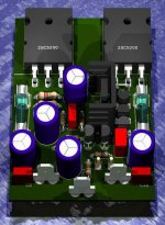
Here is, an artistic view, from the board designed by Greg Ekstine
See the beautifull work he done.
This circuit is the 25W Graham, already published design, the one that was also published in a famous Electronics Magazine.
ahahahaha!...those metalic supply posts, the flat pins are Aksa design!
regards,
Carlos
See the beautifull work he done.
This circuit is the 25W Graham, already published design, the one that was also published in a famous Electronics Magazine.
ahahahaha!...those metalic supply posts, the flat pins are Aksa design!
regards,
Carlos
Attachments
Hi Carlos,
Yes, Greg's pcb has excellent potential.
It has a central star earth right at the input transistors, and if the VAS, output wiring and Zobel components are kept away from the input, it would be a good basis for the development of a GEM pcb.
I would not be up to doing that myself. The last pcb I made was a batch for sub-miniature TENS units about 15 years ago. Been using stripboard since then.
Hi Hugh,
As promised I am responding to your enquiry in another thread.
You asked me how the upper NPN output devices work in class-A in the GEM circuit.
At quiescent the upper NPN power devices conduct approx 210mA each.
Total upper half current is approx 500mA, this including the bias plus upper driver current.
At quiescent the lower PNP power devices conduct approx 50mA each.
At quiescent the lower NPN power device conducts approx 360mA.
Total lower half current is approx 470mA.
The VAS conducts output bias current of approx 30mA.
Currents approx and not critical.
For large positive output the upper NPN devices conduct and the lower PNP go off, but the lower NPN retains class-A output control through crossover with reducing though continuous low level conduction up to maximum output.
For negative output the lower PNP devices conduct and the upper NPN will go off before the driver, but, with good output transistors and appropriate biasing and sufficient rail headroom the upper driver transistor maintains low level conduction up to maximum output. Again the lower NPN retains class-A output control through output device crossover, but it does not conduct much more than quiescent.
With loudspeaker impedance dips output will be maintained in class-AB to output device limits, but the class-AB crossovers will still be controlled by class-A conduction in both halves.
I originally had 680 ohms where there is now 820 ohms in the bootstrap bias chain and this had better class-A retention, but I felt output class-AB drive capability was by then unnecessarily large.
Carlos tested the circuit without the VAS emitter driven class-A NPN in place but he was not as happy with the results.
My desire is for fast JLH circuit class-A control activity but with class-AB power.
Cheers ......... Graham.
Yes, now i include the class A NPN, the extra transistor, the corrector....
is again running in the circuit.
Sounds better that way, now i can discriminate, separate the girls voice...having atention i can hear those girls individually, as they enter with some delay, one related the other... we can "tune" the voice and perceive.
The same effect we have hearing SSB radio transmissions and 3 persons talking at the same time, and all them around the same pitch,but with different voices and audio levels related amplitude.
The good radios, and they are not the more expensive ones, can separate those voices, you can concentrate in some guys you have more interest, and with the aid of your brain, and experience, you can hear the one, despite some "parrots" are over the same frequency, with the same "pitch" or even with a sligth different "pitch"
I could not listen to many amplifiers that can do that in Pepino di Capri CD..... the music is the old and good "Let's twist Again"... the more clear voice is from Antonela.
Those 13 hertz tone you have in your test CD are wonderfull, reproduced full power..... the vibration could shake my balls....yeah!...i have some tenis balls over the table,to exercise my hands muscle...ahahahahha...hard to catch me.... as a Roadrunner....bip bip!...Vruummm!
regards,
Carlos
Class A
Hi
I am new on this thread.
i have some questions to guys like Carlos who has experimented many amps and Graham who design thems.
I have tried JLH amp and asked me if the Graham 25W-8 with differential input will be better.
I have tried 2 JLH amp: the original 4 transistors and the dc coupled version.
The GM amp is too powerfull for my speakers: 94db 1w 1m.
The original is powerfull enough: only quality matters.
Have a good day
There are differences that keep 25W Graham amplifier ahead of JLH 1969 design, the
one is offered in Kit form by Rodd Elliot (almost the same).
The difference is very small, and was not easy to perceive in a controlled A to B comparison, when you have to use 5 watts to both amplifiers.
The power used, was a need because of JLH low power.... this way, the advantage in dinamics did not appear in that test, and also the sound stage was not judged.
It took more than one hour, and 8 guys hearing and evaluating to decide the one that was better, in a fair and controled, a very honest A to B comparison.
In you sittuation, having so efficient speaker, i think you will have more problems with 25W GEM, or even with this new 50W GEM, than continue to use your JLH, because the speakers.
You have something very near to the best we can have in class A, the best you can make to increase quality, is keep on trying to evolute your room acoustic, absorbing reflections, turning more confortable your listening position and dedicate yourself to select the better recordings and sound sources.... if not already done.
This is my idea, but Graham know more than i know, and also constructed amplifiers whole life,and was more focused in the class A subject for decades...while i was trying every new design that i found ...he continued concentrated in create something so good, or even better than JLH, having more power and less heat.... let's wait him appear to give his idea....i am sure, his evaluations are more valuable than mine.
Graham has not that very common "idiotic" characteristic, that we can find in many designers, that his own amplifiers are always better than others...i have strong evidences that he is really humble, serious and dedicated to the truth, never defending his units only because he made them...he knows the week point of every design he made, and have the good sense to use JLH as a reference design.
There are others that, in some snobish way, say that "have never listened to JLH", or "have never compared his units to JLH"
I guarantee that Graham is not this kind of man....so...he is someone to trust!
Also he do not sell nothing, have not electronics industry, no intention to provide Kits, and have the most precious "gold" that we can have on earth.... a stable and happy family.
regards Dragon 2
Carlos

Let's try again!
Hi,
Thank you for the feedback Graham. Much appreciated and informative.
I was trying to produce a single PCB so that a variety of readers could try the design out. However I understand why this would compromise the end product and therefore I will change the layout as suggested.
Regarding the second input connector is it connected directly to the first or does it have it's own input filter? A great idea by the way.
If anyone has any other requirements please advise soon.
Regards
questions, questions
Hi guys,
I can see that this amp is really something and I think that I would build it as soon as I finish the hood amp.....
But - - I have some questions in order to do that....
- how to bias the currents actually - I have read the post from mr. carlos and mr. maynard and i understand it but - in which positions to put the pot's before i turn the amp on for the first time - i am looking at the sch of the post 3 of this thread and I think that the pot for class a should be near 0 position (not near 100); also the pot for the class ab operation should be near 0 and not near 1k - before the first power on. Then we should procide like mr. carlos and mr. maynard said - am i right ??????
- how big the heatsinks - oC/W per ch.???????? I know that Iq=500mA when not playing music - but what is the max disipation - to calculate the heatsinks??!
sorry that i ask those q's among such smart guys - but i am not used to work with transistors and the topology is not very familiar to me
also i feel that there might be a few guys that ask themselves the same q's but simply don't ask them :....
best regards
Hi Sunrise,
I never thought to state heatsink size, because I know mine is okay, and Carlos' is bigger than mine. (Okay, keep it clean!)
Mine is 123 wide x 200 long x 40 fins (all mm.) and 0.7 degC/W.
All the plastic devices are on it, the outputs with little thermapads, and the fins are clearly exposed to generate convection airflow.
36W x 0.7 = approx 25 degrees; touchable but on the limit of permanently holdability.
At higher power it does get hotter, but because the class-A reduces as the AB increases - not too hot, and it does cool to normal quiescent heat soon afterwards.
Yes those are the correct pre-set adjustments that should be adjusted with a multimeter prior to switch-on.
Hi Barryblue,
I just parallel the inputs at the end of a short screened input cable.
You could work backwards from the terminal pins of Greg's illustrated pcb.
Hi Stocker and Carlos,
Both right.
I would suggest it depends upon the loudspeaker in use whether any difference can be heard; ie. if the speaker is full range and low back-EMF any difference between original amplifier types and those with differential input might not be audible.
However, with complex loudspeaker systems having an additional tweeter it is possible for the female voice tones that Carlos analyses to become slightly muddied on the original JLH due to the imbalanced hf slewing capabilities.
Other designers overcome this by incuding an upper driver transistor to counter the slight weakness in JLH positive slew, and these might well perform better when complex loudspeaker systems are used.
Carlos has mentioned the kit offered by Rod Elliot, it has that extra transistor when compared to the JLH. Then if you look at my circuit and cover the PNP output drivers in my output stage then you will see the output stage of the GEM resembles that of Rod's, which in turn resembles the JLH if you cover the upper driver transitor as well.
Hi Dragon2,
My 25W-8 is capable of making loudspeakers reproduce with better definition than the original JLH, especially with regard to phase linearity in the bass region and hf clarity, but it depends on your source and speaker whether you will actually hear it !
This circuit was designed before I started trying base-emitter capacitors to maintain closed loop stability.
The 25W-8 could very likely oscillate, though each construction may be easily stabilised by fitting appropriate R+C between differential collectors, or a C.dom between base and emitter of the phase splitting transistor. Even with these components I judge the circuit to be better than the original JLH.
However, these components act upon the af signal path, and thus my 25W-8 might be better with the 10nF and 220nF capacitors at differential stage and mirror, and a slightly reduced differential tail current, as per the GEM circuit.
The 25W-8 might have improved accuracy and damping, but because it has the same output stage it still has the positive slew weakness of the original JLH. Rod Elliot's design counters this weakness. However I did not give up in trying to find my own improvement because I also wanted more power for the heat. This positive slew weakness shows up when trying to drive complex loudspeakers (it does not arise with full-range driver types) and with the much greater heat dissipation than power output I won't go backwards to try further improving the 25W-8.
I judge the GEM to be fractionally better again because it has reduced low level hf distortion and it provides more accurate dynamic loudspeaker control. It also runs with one third of the heat dissipation, for four times the power output.
The rated 100W is for 4 ohms; ie. 50W with 8 ohms. Drop the rails to 30V or 25V to give yourself the chosen 35W or 25W output, but bias with the same currents, or more if would like to have maximum class-A operation. I suggest you won't regret it.
Cheers .......... Graham.
Well, Graham clarified completely the doubts.
My heatsink is bigger than Graham.
have two separated blocks..this way i do not use insulator material to some transistors.
Each block have 200 by 200 milimeters and each block have 15 fins that have 50 milimeters high each one.
Both blocks together, placed in the correct position, can dissipate 380 watts of heat continuously.
Aproximate calculation is:
Each fin have 20 centimeters long and 5 centimeter high.... so, each fin has 100 square centimeters exposed to air (considering only one side).... there are 30 fins....so....30 multiplied by 100 resulted in 3000 squared centimeters.
The base measure 20 by 20 centimeters... imagine as a plate without fins... so, multiplying 20 by 20 will result in 400 squared centimeter each base (were the fins are placed, the horizontal base surface).... two bases will result in 800 squared centimeters.
So...now add the fins area plus the base areas.... resulting 3800 ...divide by 10 (a practical factor that i discovered) and will result in 380 safe heatsinking capabilities...not precise, but have been working last 45 years.
Those heatsinks blocks, together, worked in an old television Radio frequency power transmitter, and the dissipation over it was exactly 400 watts, a class A transmitter that produced 50 watts of power....yeah!.... very inneficient they were...now they are junk...satelite is doing all the job...no more television point to point VHF transmiters anymore.
I am not using normal convection position because it is over dimensioned and i have a fan attached to them...forcing the air to cross the fins in an horizontal way.
The heatsink temperature do not reach 40 degrees celsius, as i left a termometer touching the aluminium in one place that the fan wind could not disturb the heat measurement.
They are only warm.... and the transistors cover have the same temperature than the heatsink...so...heat transference is OK!
The exception i have is the extra NPN...this one, beeing a TIP35, have a little bit more heat over the transistor plastic than the heatsink.... the reason why is because this transistor have not good heat transference...hummmm, very bad this one i have here!
regards,
Carlos
Re: Well, Graham clarified completely the doubts.
Thanks for the reply - have just the right size....
Thanks Carlos - and for the calculation also
best regards and keep up the good work

Graham Maynard said:Hi Sunrise,
I never thought to state heatsink size, because I know mine is okay, and Carlos' is bigger than mine. (Okay, keep it clean!)
Mine is 123 wide x 200 long x 40 fins (all mm.) and 0.7 degC/W.
All the plastic devices are on it, the outputs with little thermapads, and the fins are clearly exposed to generate convection airflow.
36W x 0.7 = approx 25 degrees; touchable but on the limit of permanently holdability.
At higher power it does get hotter, but because the class-A reduces as the AB increases - not too hot, and it does cool to normal quiescent heat soon afterwards.
Yes those are the correct pre-set adjustments that should be adjusted with a multimeter prior to switch-on.
Thanks for the reply - have just the right size....
destroyer X said:My heatsink is bigger than Graham.
have two separated blocks..this way i do not use insulator material to some transistors.
Each block have 200 by 200 milimeters and each block have 15 fins that have 50 milimeters high each one.
Both blocks together, placed in the correct position, can dissipate 380 watts of heat continuously.
Thanks Carlos - and for the calculation also
best regards and keep up the good work
well not everything has been cleared in my mind - sorry - I am still reading this thread from the beggining.....
I wonder - there is no dc offset trim.....
I know that I must pair the input diff. pair. Should I pair everything else also - so that I have small dc offset at the output (I belive that carlos said that he currently has output devices with different hfe - 90 and 105 (or 110 - I don't remeber correctly).
best regards
Yes, my output is not matched, exactly as you said.
But the input differential is matched with 10 percent difference.
Off set is very low....but if not...lets say 20 milivolts!
This will represent 100 microwatts over 4 ohms speaker.... this is nothing, and will create small problems related the distortion.
The speaker will be happy receiving some electrons crossing it.
regards,
Carlos
thanks Carlos,
that is really remarkable - that goes to mr. Maynard- really very good work.... and interesting too.
I am currently trying to find some dealer for SanKen - heard so much about them and would like to incorporate them in this project or at least toshiba transistors .....
question - where do You buy 2sa3421 and 2sa1358 if You are from Europe ???? I can't find them.......
thanks Carlos for all the replies
Hi !
Well, at least you could get the good sankens (2sc2922,2sa1216)
for ~4€ at www.schuro.de ! (originals)
Or at www.reichelt.de ... they have 2sa1358 for 61cents, but no idea
which manufacturer.
Mike
Well, at least you could get the good sankens (2sc2922,2sa1216)
for ~4€ at www.schuro.de ! (originals)
Or at www.reichelt.de ... they have 2sa1358 for 61cents, but no idea
which manufacturer.
Mike
MikeB said:Hi !
Well, at least you could get the good sankens (2sc2922,2sa1216)
for ~4€ at www.schuro.de ! (originals)
Or at www.reichelt.de ... they have 2sa1358 for 61cents, but no idea
which manufacturer.
Mike
Dear Sir - You are giving me a hard time since You have also build a great amplifier(s). I couldn't decide which one to make (I hope that I will make them both (GEM and Symasym)....
Thanks for the kind reply - I can find power transistors - - 2sa1943, 2sc5200 can be found..... The problem is to find those small ones like 2sa1358 and 2sc3421.... I guess that I would have to go on the Carlos choice of the parts bd139/140 and those bc*** - I can't remeber them right now - he talked about them few pages earlier..... If any info's about 2sa1358 and 2sc3421 it would be helpfull...... I have looked on digikey, farnell, rs, burklin and nothing....

oh - well - i'm in no hurry - i have still a lot to do on a hood amp for my friend......... so this can wait a little bit... and i can keep lookin'
thanks again for the nice reply and thanks for the nice amp and Your kindness to share it with us......

best regards
- Status
- This old topic is closed. If you want to reopen this topic, contact a moderator using the "Report Post" button.
- Home
- Amplifiers
- Solid State
- Incredible quality amplifier by Graham, prepare your ears for it