Hi All....
Yes its after midnight...
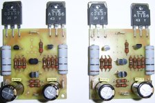
Just put some bits on the le monstre take 2.....
this time it has special bits on it....
all 0.5 W 1% resistors are tantalum or should i say - unobtanium
the two 5W power resistors are metal oxide non inductive...
the caps are ELNA Cerafines, the transistors are all matched originals, the JFETS are all matched originals, the output stage is the only thing non original it is upgraded to Sanken 2SA1186/2SC2837... much faster / lower Cob.
i superglued the small signal stuff together to enhance thermal tracking.
any how i need one more part which is the dc offset trimpot i will get a multiturn one tommorrow....
then its time to power up this little beasty...
-Dan
Yes its after midnight...
Just put some bits on the le monstre take 2.....
this time it has special bits on it....
all 0.5 W 1% resistors are tantalum or should i say - unobtanium
the two 5W power resistors are metal oxide non inductive...
the caps are ELNA Cerafines, the transistors are all matched originals, the JFETS are all matched originals, the output stage is the only thing non original it is upgraded to Sanken 2SA1186/2SC2837... much faster / lower Cob.
i superglued the small signal stuff together to enhance thermal tracking.
any how i need one more part which is the dc offset trimpot i will get a multiturn one tommorrow....
then its time to power up this little beasty...
-Dan
Attachments
Just fired it up in my break....
Had to trim the bias down from 2.4A !!!!! adding a 1k in parallel with the existing 1K biass resistor yeilds 1.01-1.05A stable.
I did notice a couple of things if anyone is build one.
if you wait for the amp to get stable once you have set the one amp bias you can achieve <10mV with a 25 turn pot easily. with quite low drift. +/- 5mV
The bias level is quite critical for stability at 8R high power at high frequency.
ie if you have 2+ Amps bias on this one it is/was not stable at >20kHz with max output. (i think the 716/756 pair begins to become saturated)
once you have 1 Amp... the amp is very stable. I was able to achieve over 1MHz.
I will post some Scope/MSO pics when i get a chance.
-Dan
Ok....
to save people who dont want large-ish images loading please see here for the le monstre MSo shots.
notice these is some ringing on the square waves at higher frequencies.
I will work out a cure for this. however i think it is just the measurement setup leads etc.
http://s300.photobucket.com/albums/nn26/danw1million/?action=view¤t=000.jpg
-Dan
Daniel,
So the PCBs work fine, I am very glad about it")
I just got some shinkohs and I will soon post some components for selling if anyone wants to build this at a lower cost.
I have found greater wattage shinkohs (1-3W) but I have found all of them! VERY costy though...
I have some questions about your build.
Firstly, how you sold the input transistors together? Is it some special paste or just the standard white ceramic thermocouple paste?
Secondly, since I am at the final stage of building it too as you know, I would like you to describe in details the bias tuning process (where you connect the ampmetter, what adjustments, what values etc, is there any case of burning out the transistors if bias is wrong for a lot of time etc).
I think it will be fery helpfull for me as well for the other members that build this monstre
So you are building it using only batteries or mixed mode?
So the PCBs work fine, I am very glad about it
I just got some shinkohs and I will soon post some components for selling if anyone wants to build this at a lower cost.
I have found greater wattage shinkohs (1-3W) but I have found all of them! VERY costy though...
I have some questions about your build.
Firstly, how you sold the input transistors together? Is it some special paste or just the standard white ceramic thermocouple paste?
Secondly, since I am at the final stage of building it too as you know, I would like you to describe in details the bias tuning process (where you connect the ampmetter, what adjustments, what values etc, is there any case of burning out the transistors if bias is wrong for a lot of time etc).
I think it will be fery helpfull for me as well for the other members that build this monstre
So you are building it using only batteries or mixed mode?
Daniel,
So the PCBs work fine, I am very glad about itYes very happy they are nice and neat thanks !!!!
I just got some shinkohs and I will soon post some components for selling if anyone wants to build this at a lower cost.good idea
I have found greater wattage shinkohs (1-3W) but I have found all of them! VERY costy though...well done they are quite hard to find all the right values !!!!
I have some questions about your build.
Firstly, how you sold the input transistors together? Is it some special paste or just the standard white ceramic thermocouple paste?i used a tiny dot of super glue
Secondly, since I am at the final stage of building it too as you know, I would like you to describe in details the bias tuning process (where you connect the ampmetter, what adjustments, what values etc, is there any case of burning out the transistors if bias is wrong for a lot of time etc).
I think it will be fery helpfull for me as well for the other members that build this monstrei just tested it today. and the bias started at 2.4A which is more than double. the temp rises quite quickly however it is not thats dangerous as long as its only for say a few second or so. the value which gave me 1.01-1.05A bias was 500 Ohms. my suggestion is start at 1k and decrease until you get 1A using fixed resistors. in paralell
So you are building it using only batteries or mixed mode? I just tried it with a lab supply... i will try with batteries when i can afford some !!!!!!!!!!!!!!! let me know how your building goes !!!!
Just a quick question (a bit silly though, but just to make sure)
Where do you connect the ampmetter to measure the bias?
Where do you connect the ampmetter to measure the bias?
Daniel,
So the PCBs work fine, I am very glad about itYes very happy they are nice and neat thanks !!!!
I just got some shinkohs and I will soon post some components for selling if anyone wants to build this at a lower cost.good idea
I have found greater wattage shinkohs (1-3W) but I have found all of them! VERY costy though...well done they are quite hard to find all the right values !!!!
I have some questions about your build.
Firstly, how you sold the input transistors together? Is it some special paste or just the standard white ceramic thermocouple paste?i used a tiny dot of super glue
Secondly, since I am at the final stage of building it too as you know, I would like you to describe in details the bias tuning process (where you connect the ampmetter, what adjustments, what values etc, is there any case of burning out the transistors if bias is wrong for a lot of time etc).
I think it will be fery helpfull for me as well for the other members that build this monstrei just tested it today. and the bias started at 2.4A which is more than double. the temp rises quite quickly however it is not thats dangerous as long as its only for say a few second or so. the value which gave me 1.01-1.05A bias was 500 Ohms. my suggestion is start at 1k and decrease until you get 1A using fixed resistors. in paralell
So you are building it using only batteries or mixed mode? I just tried it with a lab supply... i will try with batteries when i can afford some !!!!!!!!!!!!!!! let me know how your building goes !!!!
Just a quick question (a bit silly though, but just to make sure)
Where do you connect the ampmetter to measure the bias?
Measure voltage across the 1 ohm resistors and convert.
bobodioulasso is right
two reasons, this way you dont have the resistance of the current meter in series with the circuit. only the high impedance of the voltmeter which is usually much greater and less signicficant.
also the value of the resistor is 1 Ohm so it is convenient.
1A through 1 Ohm = 1V
nice eh.
-Dan
two reasons, this way you dont have the resistance of the current meter in series with the circuit. only the high impedance of the voltmeter which is usually much greater and less signicficant.
also the value of the resistor is 1 Ohm so it is convenient.
1A through 1 Ohm = 1V
nice eh.
-Dan
Here is a thought / question...
if you notice in my earlier post i linked to the waveforms:
http://s300.photobucket.com/albums/nn26/danw1million/
The output stage i am using now is so fast it has some overshoot
do you think the original @ 15MHz is better because it was "slower"
??
any thoughts
-Dan
if you notice in my earlier post i linked to the waveforms:
http://s300.photobucket.com/albums/nn26/danw1million/
The output stage i am using now is so fast it has some overshoot
do you think the original @ 15MHz is better because it was "slower"
??
any thoughts
-Dan
Parts for sale
Ok the time has come to sell this bag of parts for the "Le Monstre"
All the quality parts at once!
Apart from the output transistors and trimmers you need nothing more to build the amplifier
Check this page:
http://audio-constructions.com/monstre/parts/
Good luck
Ok the time has come to sell this bag of parts for the "Le Monstre"
All the quality parts at once!
Apart from the output transistors and trimmers you need nothing more to build the amplifier
Check this page:
http://audio-constructions.com/monstre/parts/
Good luck
Just fired it up in my break....
Had to trim the bias down from 2.4A !!!!! adding a 1k in parallel with the existing 1K biass resistor yeilds 1.01-1.05A stable.
-Dan
1. So the 1K should be replaced by 500R ? Is this replacement specific for the transistors you have used or does it have to be about 1K if using the original output transistors?
2. Also for the 1.01-1.05A, you refer to the quiescent current through EACH 1ohm resistor? (because in the original article it states it sould be 0.5-0.6A)
3. An interesting point is to make a circuit to continuously correct the bias, by measutig the voltage accross 1Ohm resistors and altering the falue of a parallel resistor to the 1K one. So the bias would always be in the correct point. (very usefull if running in battery only operation, where the voltage changes as the battery discharges.)
Last edited:
1. So the 1K should be replaced by 500R ? Is this replacement specific for the transistors you have used or does it have to be about 1K if using the original output transistors?
2. Also for the 1.01-1.05A, you refer to the quiescent current through EACH 1ohm resistor? (because in the original article it states it sould be 0.5-0.6A)
3. An interesting point is to make a circuit to continuously correct the bias, by measutig the voltage accross 1Ohm resistors and altering the falue of a parallel resistor to the 1K one. So the bias would always be in the correct point. (very usefull if running in battery only operation, where the voltage changes as the battery discharges.)
Yes the bias i am running at the moment is 1A with the output stage i chose i needed 500R to achieve this.
I may bring the bias lower to see how it affects the performance.
I thought the original bias was 1A have i will have another look.
-Dan
"One should not lose sight of the fact that the 8W functions in class A. The quiescent current therefore has a prime importance. Its value should not be too low otherwise the amplifier will pass into class AB on strong signals, nor too high because it would impose too great a dis*sipation on the power transistors which, in addition to the fact of limiting their lifespan, can lead to thermal runaway. Indeed, the characteristics of the power transistors are related to the temperature of the junctions and beyond a certain threshold there is runaway, that is to say the more the temperature rises the more the current increases. The optimal value lies between 0.5 and 0.6A. "
from the translation on your site....
I better reduce that value !!!!
more testing before it hits the speakers.... it is definately friday !
from the translation on your site....
I better reduce that value !!!!
more testing before it hits the speakers.... it is definately friday !
"One should not lose sight of the fact that the 8W functions in class A. The quiescent current therefore has a prime importance. Its value should not be too low otherwise the amplifier will pass into class AB on strong signals, nor too high because it would impose too great a dis*sipation on the power transistors which, in addition to the fact of limiting their lifespan, can lead to thermal runaway. Indeed, the characteristics of the power transistors are related to the temperature of the junctions and beyond a certain threshold there is runaway, that is to say the more the temperature rises the more the current increases. The optimal value lies between 0.5 and 0.6A. "
from the translation on your site....
I better reduce that value !!!!
more testing before it hits the speakers.... it is definately friday !
Yes that was exactly the point I was reading too.
hm.. I found the simplest solution for the autobias! It is something like this http://diyaudioprojects.com/Solid/DIY-Lightspeed-Passive-Attenuator/
just use LDRs.
But one should chose a specific LDR which will give a resistance of 500ohm to 900ohm, when paralleled with 1K. i.e the LDR should have a resistance of about 1-10K. A scaling mechanism must exist there, to compenstate correctly to the voltage variations.
So as far as I think just decide the bias point and then chose the appropriate LDR.
In a fixed PSU this is not much of importance but in battery only mode this is crucial I think, unless you want to continuously set the bias as the batteries are gedding discharged.
hey you may even compensate for the differences in batteries discharging that way? (one battery may discharge a bit quicker than the other, or may not be as charged as the other). (crazy thought?)
- Home
- Amplifiers
- Solid State
- Hiraga "Le Monstre"