hello everyone!
i am new one here and registered basically after reading this thread across several times.
i got 640a v1 and use it constantly since 2004 (if i remember right).
already ordered caps (elna & nichicon) to do full recap and thinking about changing opamp/s as well.
wanted to ask few questions guys, as i am neither at pro or amateur level in electronics.
is it worth changing opamps in amplifier other than in U5 slot, which is best seen on pic by whaleman #93?
i believe that some opamps are better than ne5532/34's used in 640a, isn't it?
thinking of ordering LME49860 to use in U5.
would be glad to see any comments of you.
thanks!
replaced 8 x 2200uF caps in the power supply with Nichicon 3300uF FW series.
full list of caps i used:
10 Nichicon ES 10uf / 25v
8 Elna Silmic II 220uF / 50V
2 Nichicon ES 100uf / 25V
1 Nichicon FG 1uf / 50V
4 Elna Silmic II 220uF 16V
2 Elna Silmic II 10 uF 25V
2 Elna Silmic II 100 uF 25V
1 Elna Silmic II 100 uF 35V
1 Elna Silmic II 47uF 16V
2 Elna Silmic II 100uF 16V
2 Nichicon KZ 47uf / 50V
1 Nichicon FG 470uf / 35V
8 Nichicon FW 3300uf / 50V
first impression after i turned it on - WOW!!!1
after 10 years of almost everyday use i can notice the difference now.
smoother, easy driven bass, clearer sounding overall.
then i changed op-amp in U5 to LME49860, it gave more air and space; don't know how better to express my feelings. although, that impression might be blurred by full recap i did before installing op-amp.
anyway, here are some pics:
Attachments
Hi guys
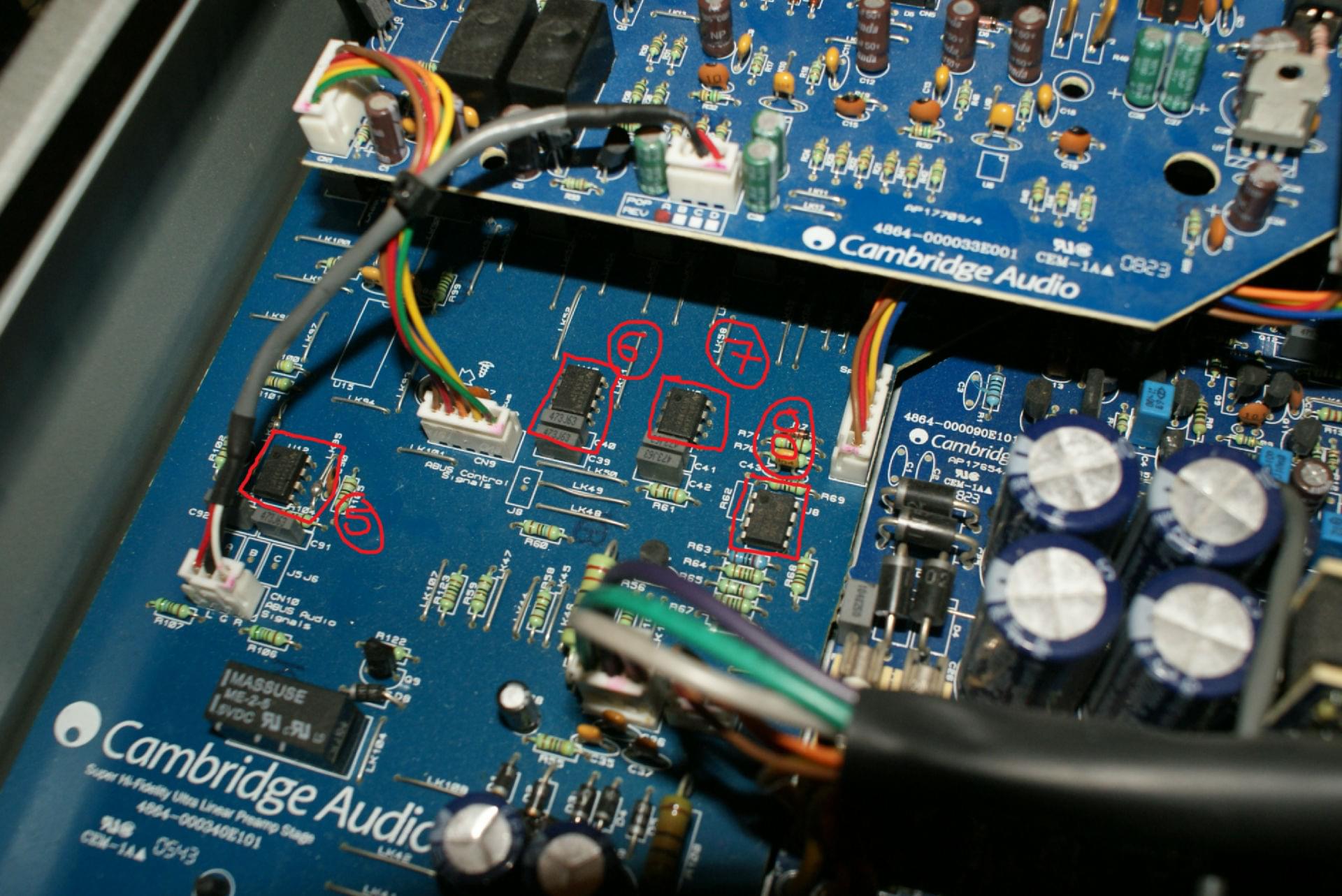
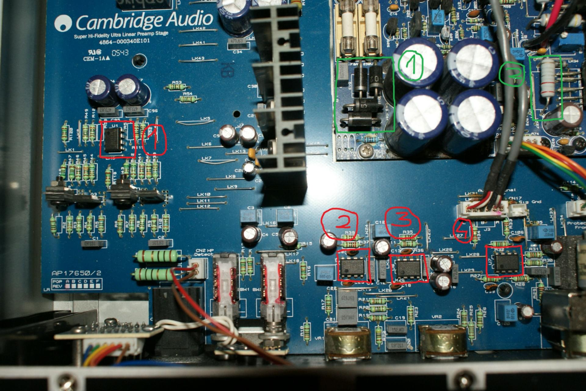
I also new here. I'm mooding my 640a v2 a alredy order conds") but pre section in my v2 is a little bit diffrent than v1. V1 has got 3 opamp's and mine has got 4. So my question is with opamp should be change to give the sound just like you wrote about it. I think it should be u7... maby pictures will help you. There are some of those:
but pre section in my v2 is a little bit diffrent than v1. V1 has got 3 opamp's and mine has got 4. So my question is with opamp should be change to give the sound just like you wrote about it. I think it should be u7... maby pictures will help you. There are some of those:
[img=http://images41.fotosik.pl/1346/c0bba55999c870c4.jpg]
[img=http://images41.fotosik.pl/1346/f239b066f82848c2.jpg]
Chears Lukas
I also new here. I'm mooding my 640a v2 a alredy order conds
but pre section in my v2 is a little bit diffrent than v1. V1 has got 3 opamp's and mine has got 4. So my question is with opamp should be change to give the sound just like you wrote about it. I think it should be u7... maby pictures will help you. There are some of those: [img=http://images41.fotosik.pl/1346/c0bba55999c870c4.jpg]
[img=http://images41.fotosik.pl/1346/f239b066f82848c2.jpg]
Chears Lukas
Last edited:
"From what I've read, it is not at all sufficient for 640A's 65 watt power. "
You're reading the wrong stuff.
The 10,000W Crown uses one 10,000µF cap, that's it.
"seems that 4700uF caps are not enough for 400W RMS for two channels or one channel"
The values for power supply capacitance can be realistically determined by a consideration of the numerical value of W C R where W is the line frequency (377 rad/sec), C is the power supply capacitance, and R is the load resistance. An WCR value of 10 yields about 10 per cent ripple (pk.-pk. ) and a value of 100 has about two percent. Below 10, the power supply will have serious problems and values of about 100 will achieve diminishing performance returns. The minimum value then, for each of the four power supply capacitors should be about 3,000uF and the maximum about 30,00OuF. Capacitances above this value may cause diode bridge failure due to turn-on surges and are not recommended.
(http://www.passdiy.com/pdf/a40.pdf)
3,300µF x2 for one channel at 8Ω with 60hz line (3,900µF for 50hz), double for 4Ω, double again for 2Ω.
Example: Crest CA9 has a tiered supply and 120,000µF total capacitance. This is 15,000µF per channel, per tier, the 10% ripple point.
Remember, stored energy increases with the square of the voltage, so a 3,300µF cap with 100V on it stores 4x the energy that a 3,300µF cap with 50V on it stores.
radian per second = W
f*2Pi=W
377 (60hz)
314 (50hz)
Page 2 there are my pictures http://http://www.audiostereo.pl/problem-z-cambridge-audio-640-v2_92211.html/page__st__30
Hi guys
I also new here. I'm mooding my 640a v2 a alredy order conds
[img=http://images41.fotosik.pl/1346/c0bba55999c870c4.jpg]
[img=http://images41.fotosik.pl/1346/f239b066f82848c2.jpg]
Chears Lukas
I think you are correct, it is U7 from what I can tell in your pictures (marked as 4). I did not have good success replacing op amps except for this last one buffer op amp before the power amp, nearest to the volume control. I would use a socket so it can allow you to try the "best fit" sound and "roll" some op amps. I found Burr-Brown OPA2134 was good, and AD8599 was great. Both much better than the stock NE5532. Changing the tone control op amps was a waste of time, I had to revert back to the original and that goes for the rest of the op amps in the unit. Keep in mind though that I have V1. While you are in there, organize your wires away from the heat sink.
Good evening all,
I have modified my CA 540A a couple of years back.
Similar schematic to CA 640A.
Schottky diode on power rail,
Bigger caps at power rails and beside opamps,
Removed coupling caps from signal path,
Replaced pots, except volume,
Installed sockets for opamps and replaced opamp to 4562 (I thing),
Installed screen on cables going across board.
I have service manuals for some models of CA, please contact me if interested.
Best regards.
Sasha.
Hello Decky,
Attaced is the link to the service manual I used, it is revised May 2008, and as far as I remember it was quite accurate, still I gave up on the CA 640A v2 I had and sold it. Simply did not like the sound of it.
Anyway, this is the link, hope it helps:
640A Integrated Amplifier free ebook download
Saludos,
Manuel
Thanks Manuel
I have that one - it is accurate but there are more than few differences between V1 and V2. I am especially curious about that protection implementation. I am suspicious that is plays some funny games with me - hopefully that controller is still in one piece. I also did a mod of V1 and that sounded lovely - hoping that V2 would be better - fools hope? Maybe?
I have that one - it is accurate but there are more than few differences between V1 and V2. I am especially curious about that protection implementation. I am suspicious that is plays some funny games with me - hopefully that controller is still in one piece. I also did a mod of V1 and that sounded lovely - hoping that V2 would be better - fools hope? Maybe?
- Home
- Amplifiers
- Solid State
- Modding Azur 640A