hienrich said:kanwar: how do we know that damping factor is actually improve?
can we hear it?
and if we can hear it what is its form or I mean in aform of what?
reagrds;
hienrich
Yes you can exactly hear it.
Play the music with subsonic bass content and see the movement of speaker cone , in case of VAS with resistors it will be less compared to without resistors, its lot cone movement. just a simple fact.
its only for you Quasi
Hi Quasi,
I have an upgrade sort of thing for your amp.
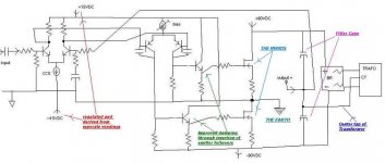
1. Supply Requirements +-15VDC regulated for Driver stage & +-90VDC unregulated for output Mosfets..
2. Reversed output type i.e. output node of mosfets acts as an earth reference and center tap of caps+trafo acts as an output...
3. Additional damping factor improved by using emitter followers prior to mosfets yet Maintaining R2R operation...
If you are interested than i could post the layout.....
K a n w a r
Hi Quasi,
I have an upgrade sort of thing for your amp.
1. Supply Requirements +-15VDC regulated for Driver stage & +-90VDC unregulated for output Mosfets..
2. Reversed output type i.e. output node of mosfets acts as an earth reference and center tap of caps+trafo acts as an output...
3. Additional damping factor improved by using emitter followers prior to mosfets yet Maintaining R2R operation...
If you are interested than i could post the layout.....
K a n w a r
Hi Kanwar,
You must know that the second diff'l pair is not having the good behaviour as one half will have twice the Pd so will drift, also no emitter degeneration. This also is slowed with C and placing more demand on first stage current.
Oh, goodness me, you have floating PS and grounded output - so both your output stages can be, seemingly, 'grounded' output but supply is now floating and not bypassed with big C to ground - I think you are swapping halves for problem.
Cheers,
Greg
Hi Greg,
The emitter degeneration are must for there...only emitted in layout due to simplycity....
The first differential current is set at 3mA per device and second differential is at 8mA per device sothere would be no problem regarding drifting as long as the devices are mounted on heatsink..
Secondly to EF stage is at idle current of about 20mA and thus drives the output mosfets well enough with good damping due to increased current gain from the previous version....
Regarding grounded output, it simply doesn't pose a problem because the driver stage is well regulated and isolated and its earth reference is just connected to the output well enough and I have used this circuit for powering the subwoofers 2 years ago without any problem regarding filteration ....
Damping was excellent enough to restrict the woofers within their limits of XMAX[excursion].....
Meanwhile QSC also uses grounded output node and Crown also uses grounded bridge which have same operation basic grounding principle and have no ill-effect on the performance...
regards,
K a n w a r
Hi Kanwar,
I have also tried the emitter followers on this amp with a few hundred milliamps running through these. This provided for a very low impedance drive to the output stage. But this stage ran really hot.
Instead of this I opted for the cascode second stage as posted in the high power version. There is no reason why this stage can't run at say 100mA or more as there is only a couple of volts across the driver transistors.
I like the idea of the regulated power supply to the input stage.
Eventually though the other amp I posted in "power amp under development" continues to be superior.
Cheers
Error in PCB layout???
Quasi,
Can you tell me what is the error on PCB layout that you mention earlier in low power version.
http://www.diyaudio.com/forums/showthread.php?postid=631576#post631576
Is it a wrong placement of the 100ohm pot?
Cheers
Quasi,
Can you tell me what is the error on PCB layout that you mention earlier in low power version.
http://www.diyaudio.com/forums/showthread.php?postid=631576#post631576
Is it a wrong placement of the 100ohm pot?
Cheers
Re: Error in PCB layout???
In the first board layout the negative rail track is connected to the collector of T2 and the associated 15k resistor. This effectively shorts out the constant current source.
The corrected board is attached. Note I have not yet built this board. Please take the time to check it against the schematic before you build.
pejinm said:Quasi,
Can you tell me what is the error on PCB layout that you mention earlier in low power version.
http://www.diyaudio.com/forums/showthread.php?postid=631576#post631576
Is it a wrong placement of the 100ohm pot?
Cheers
In the first board layout the negative rail track is connected to the collector of T2 and the associated 15k resistor. This effectively shorts out the constant current source.
The corrected board is attached. Note I have not yet built this board. Please take the time to check it against the schematic before you build.

Quasi class A
Thank you Mastertech.
No I haven't. No reason why this design could not run in class-a though.
Using the low power module the changes I would make would be;
1. Lowering the main rails to around 25 volts
2. Lowering the secondary rail to 35 volts
2. Shorting R7
3. Reducing the gain (R13 / R11)
4. Cranking the bias current up to 3 amps or so (ouch).
5. Big heatsinks (150 watts will be dissipated continously per module)
6. A huge regulated & noisless power supply capable of 6 amps. ( x 2 for stereo ).
Voila ...one 35 watt class-a amp.
The above is for a practical amp ....of course you could leave the rails as they are .....but I'm sure you have adequate heating in your home. Still it would be awesome.
Cheers
mastertech said:Hey quasi My name is mastertech you are all very good quasis
i havent seen one of yours i havent liked
btw have you ever built a quassi running in class-a
thanks and out
Thank you Mastertech.
No I haven't. No reason why this design could not run in class-a though.
Using the low power module the changes I would make would be;
1. Lowering the main rails to around 25 volts
2. Lowering the secondary rail to 35 volts
2. Shorting R7
3. Reducing the gain (R13 / R11)
4. Cranking the bias current up to 3 amps or so (ouch).
5. Big heatsinks (150 watts will be dissipated continously per module)
6. A huge regulated & noisless power supply capable of 6 amps. ( x 2 for stereo ).
Voila ...one 35 watt class-a amp.
The above is for a practical amp ....of course you could leave the rails as they are .....but I'm sure you have adequate heating in your home. Still it would be awesome.
Cheers
- Status
- This old topic is closed. If you want to reopen this topic, contact a moderator using the "Report Post" button.
- Home
- Amplifiers
- Solid State
- Another quasi-complementary design