Dear Rajeev Luthra!
Here is the schematic in better quality.
http://www.audiofanatic.it/Schemi/Tipo/Stato_solido/finali/pic_finaliSS/240W_MOS_BUZ23.jpg
Regards
Here is the schematic in better quality.
http://www.audiofanatic.it/Schemi/Tipo/Stato_solido/finali/pic_finaliSS/240W_MOS_BUZ23.jpg
Regards
I have also built this design from the 1987 Siemens MOSFET databook. However as can be seen the output damping factor relies heavily on the global feedback loop. The lower output stage has a natural output impedance of 100k+. So to get down to say 1 Ohm output impedance, you need feedback factor of 80 dB. And that's global feedback!!! It's not even a very good damping.
The design is nice and simple, and will (with elevated supply for the last differential stage) give a rail loss free output power. However the bass reproduction will never be very firm and controlled. I'd say there are better ways to build an n-channel amplifier. But if you are gonna go through with it, i would suggest adding a resistor across the input terminals, this way you can avoid a giant pop when you insert a plug into the amplifier.
")
The design is nice and simple, and will (with elevated supply for the last differential stage) give a rail loss free output power. However the bass reproduction will never be very firm and controlled. I'd say there are better ways to build an n-channel amplifier. But if you are gonna go through with it, i would suggest adding a resistor across the input terminals, this way you can avoid a giant pop when you insert a plug into the amplifier.
Thanks for the circuit...
My version of the circuit is of course identical in general operation except for the following.
The constant current source for the first stage is a lot simpler in my cct and just as effective with a lower component count.
My temperature compensation for the output stage bias is a lot simpler and seems to effective enough. I am currently playing with the idea of adding another diode to this string to moderate it's response.
The drive impedance for the output FETS is too high in my view at 1k. This provides a drive stage current of only 4 milliamps and is in my view too low to effectively charge and discharge the gate.
The output resistors on the Elektor cct are on the wrong side of the FET. They should be on the FET's source. They provide localised feedback for this part of the output stage.
Lars your comments about the resistor across the input are noted with thanks.
My humble thoughts only.
Cheers
PS. I have a prototype of my version running on the bench. So far so good but it is not as quiet as the amp I built in "power amp under development". More work to do on this one.
yeah there are certainly other ways to build a n-channel amp
hello Quasi & Lars,
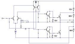
look at the schematic block diagram featuring direct cascode loading , individual floating gate drivers supplies, suprimosed supply for VAS.
What are your views regarding this type of amp.
Please comment.
regards,
kanwar
hello Quasi & Lars,
look at the schematic block diagram featuring direct cascode loading , individual floating gate drivers supplies, suprimosed supply for VAS.
What are your views regarding this type of amp.
Please comment.
regards,
kanwar
Attachments

quasi, I like your design. Keep up the good work.
kanwar, will the zener diode be your thermal compensation device? Do you really need the darlington buffer for just a pair of output devices? Also the additional 12V supply for each darlington means an over complex PSU IMO. It would be fine to connect them to the 80V rail, wouldn't it? I'm sure the dissipation would be manageable.
How about replacing the gate pulldown resistors with current sinks? That way would give nice fast turn off and less cross-conduction? However, unless the sink was set on a rail of lower voltage than the MOSFET source, it would not be able to pull down enough I think, which would be disastrous. Also, there could be a problem if the driver transistor turned off, depending on how the sink was implemented.
Ok....I'm sorry
Sorry Workhorse, jus a bit busy sometimes (I gotta work for a living etc...)
I never thought of setting up a constant current source for the second stage like you have (at least I think that's what it is). I have never been able to do better than 2 diodes on the base emitter junction (0.6v / emitter resistor etc.).
I see what you are trying to achieve with the applying only 12 volts to the second stage but I think that would be more complicate than indicated by the cct. I agree with richie00boy and would tie both the postive side and negative side transistor collectors to the positive rail. I do note though that the darlington pair on the negative side will have around 170 volts across them so SOAR could be an issue. This can be resolved though with suitable or parallel devices. In my cct I am thinking about running another set of MJE350's in parallel with current sharing resistors to split the current.
I don't think the darlington are really necessary because you would only need an overall voltage gain for the amp of around 50.
I have found that even with the raised positive rail for the input and driver stages the amp centres very nicely and does indeed drive rail to rail.
If you run 20 - 30 milliamps in the second stage then turn off issues with the output FETS will be less of an issue. You could run say 100 mA but the second stage could get very hot.
Interesting thinking Workhorse...have you tried this on the bench?
Cheers
Workhorse said:anybody with views......... comments........anything............
Sorry Workhorse, jus a bit busy sometimes (I gotta work for a living etc...)
I never thought of setting up a constant current source for the second stage like you have (at least I think that's what it is). I have never been able to do better than 2 diodes on the base emitter junction (0.6v / emitter resistor etc.).
I see what you are trying to achieve with the applying only 12 volts to the second stage but I think that would be more complicate than indicated by the cct. I agree with richie00boy and would tie both the postive side and negative side transistor collectors to the positive rail. I do note though that the darlington pair on the negative side will have around 170 volts across them so SOAR could be an issue. This can be resolved though with suitable or parallel devices. In my cct I am thinking about running another set of MJE350's in parallel with current sharing resistors to split the current.
I don't think the darlington are really necessary because you would only need an overall voltage gain for the amp of around 50.
I have found that even with the raised positive rail for the input and driver stages the amp centres very nicely and does indeed drive rail to rail.
If you run 20 - 30 milliamps in the second stage then turn off issues with the output FETS will be less of an issue. You could run say 100 mA but the second stage could get very hot.
Interesting thinking Workhorse...have you tried this on the bench?
Cheers
I like damping factor, but of course i have my own personal interpretation of that too Natural damping factor.
I will tell you why.
Try this simple experiment: Make an amplifier with high output impedance, like collector output, then use global feedback to improve the damping factor to 100. You will get a 'rubber bass' sound. Absolutely no dynamic.
Then make an amplifier with a low natural output impedance, of also 100. Like with Emitter coupled output stage. Now the bass sound is dynamic, fast and upfront. This is what you want.
As it turns out, from many many experiments (that everyone in here can easily copy) with the same damping factor you can get different bass sound, and so in my book the damping factor is (like several other models - such as THD - for evaluating audio amplifiers ) is largely ....... useless.
What will affect the bass sound though is the Natural Damping Factor. This is simply the damping factor without any amplified feedback.
Global feedback is ok, but only if the amplifier doesn't have any unlinearities, because the global feedback will not improve these problems (sonically). As i have shown in another thread, you can remove THD in unlinear circuits with a feedback loop. But you will get sidebands, that will clutter the sound performance. You will see actually i use global feedback in some of my amplifiers as a simple solution to keep it at a stable DC operating point. But these amplifiers are virtually free from unlinearities in the amplification chain.
Natural damping factor.I will tell you why.
Try this simple experiment: Make an amplifier with high output impedance, like collector output, then use global feedback to improve the damping factor to 100. You will get a 'rubber bass' sound. Absolutely no dynamic.
Then make an amplifier with a low natural output impedance, of also 100. Like with Emitter coupled output stage. Now the bass sound is dynamic, fast and upfront. This is what you want.
As it turns out, from many many experiments (that everyone in here can easily copy) with the same damping factor you can get different bass sound, and so in my book the damping factor is (like several other models - such as THD - for evaluating audio amplifiers ) is largely ....... useless.
What will affect the bass sound though is the Natural Damping Factor. This is simply the damping factor without any amplified feedback.
Global feedback is ok, but only if the amplifier doesn't have any unlinearities, because the global feedback will not improve these problems (sonically). As i have shown in another thread, you can remove THD in unlinear circuits with a feedback loop. But you will get sidebands, that will clutter the sound performance. You will see actually i use global feedback in some of my amplifiers as a simple solution to keep it at a stable DC operating point. But these amplifiers are virtually free from unlinearities in the amplification chain.
Below a sch of the last half of a basic power amplifier. I added the 2 resistors R1 and R2. They have no apperant effect, in the circuit.
What they do however is to replace the high Z of the collectors from the gain stage ( 1 Meg ) with say 10k. This gives the amplifier 100 times lower Natural Damping Factor. It also lowers the feedback factor, while maintaining the voltage amplifier's pole intact. And thus improves the stability of the amplifier. I will add in most cases, just to avoid any attacks from the tg's
Basicly it gives a lower feedback factor, and thus a higher THD, and in the same time improves the sound quality. Try it out in your own amplifier .....
In fact only one resistor is needed, but might give a slight DC offset.
Attachments
Hmmm...
Robert Cordell has done a lot to debunk all this mythology about TIM, Interface IM ad nauseum... that seems to flow from Scandinavia..
"Another View of TIM" (Audio Feb 1980),"Interface Intermodulation in Amplifiers" (Wireless WorldFeb 1983) and
"Open-loop output impedance and interface intermodulation distortion in audio power amplifiers" (AES Conv NY 1979)
I'd suggest what you're hearing with the Vas loading resistors in place is euphonic 2HD. I improve such amplifiers for clients by pulling these resistors OUT.
amplifierguru said:Robert Cordell has done a lot to debunk all this mythology about TIM, Interface IM ad nauseum... that seems to flow from Scandinavia..
[...]
I'd suggest what you're hearing with the Vas loading resistors in place is euphonic 2HD. I improve such amplifiers for clients by pulling these resistors OUT.
Just to add fuel to the fire,
there was some discussion about this a while back in another thread. See http://www.diyaudio.com/forums/showthread.php?postid=421448#post421448 and http://www.diyaudio.com/forums/showthread.php?postid=419336#post419336- Status
- This old topic is closed. If you want to reopen this topic, contact a moderator using the "Report Post" button.
- Home
- Amplifiers
- Solid State
- Another quasi-complementary design