The original Hitachi Design.
Hi all
I found the original Hitachi datasheet which discusses the use of their power MOSFETS in amplifiers, and was the source of several designs including Maplin's. It's good reading for all those interested. If you would like a copy, then e-mail me, and I'll send it.
Hi all
I found the original Hitachi datasheet which discusses the use of their power MOSFETS in amplifiers, and was the source of several designs including Maplin's. It's good reading for all those interested. If you would like a copy, then e-mail me, and I'll send it.
Maplin amp
As I said, I've used a few of these modules, two for my stereo. I noticed that the heatsink case was getting warmer than usual, and while investigating it, I noticed very high frequency oscillations on the output. I thought maybe the caps had dried out somewhat, it runs at 40 degrees case temperature normally which is ok, but maybe it shortens cap life. It's a bit cramped in there. After a change of caps, I still had the same problem. I used a different amp and shelved the problem for a rainy day.
Months later;
My sub amps use the same modules, and while modding them to suit a new active crossover, I noticed the same high frequency oscillations but at a lower level. The sub amp has a different layout, not so cluttered. How could this be? Could they have been oscillating unnoticed from the start? I paid particular attention to the sub amps, so I could not have missed it. I scope all my amps, sniffing for problems, but maybe...?
So the amps were fine when built, but developed instability over time, and it's not the caps. So what has changed? Hmmmm
The bottom line;
It turns out that the zobel resistor had burnt out in all four modules. In a sub amp with no HF signals too. I replaced the resistor with a 4R7 3W WW and there is no trace of instability on a 100MHz scope at 5mV/div sensitivity.
I find this very curious, I used the resistor specified in the kit, again 4R7 3W WW, but it burnt out in a sub amp.
So to those who may have built it, look out for this problem.
Any ideas as to the cause?
Hi johnnyx,
I've had the same problems as you with one of my amps. When everything was laying arround on my desk, everything was fine. But after I build the amp in, in an eclosure, I had some oscillation problems.
Make sure the PCB tracks to the gates of the mosfet's are as short as possible. And attach the gate resistor as close to the gates as can be. 100Ohm seems pretty low, mostly 220Ohm is used with these kind of mosfet's.
I hope you can do something with the info. Is anything changed at your power supply, best is to connect a capacitor of 100n directly between the + and - rail.
Greetz
Ben
zinsula:
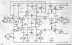
I also know these modules because I had to repair some of them that suffered from abuse and aging (not to mention that the folk who assembled them forgot to use thermal compound!!) . They indeed show poor power supply rejection, and biasing changes with supply voltage. Howerver, there is a very simple approach to circumvent that: replace the 47K resistor that biases the input LTP by two independent resistors connected in series, and connect their middle point to ground through a zener, so that it clamps the voltage to some value.
For example, in order to keep the same 1mA bias you can use a 15V zener, a 12K or 15K resistor connected to the emitters and a 10K resistor connected to the supply rail. This won't be as good as a current source, but it's a very easy modification. Note that the value of R9 may require some adjustment.
Hi bensen
Two modules were built as the kit, with the PCB as supplied. I thought that the Zobel network was to maintain stability with an inductive load. With no load, surely the amp should be stable without it? Since it isn't, then there must be some reason for the instability.
I will remove the zobel and see if I can stabilise it, first I will increase the gate resistors as you suggest. I have already increased the Miller cap, ( I used 22p polystyrene instead of 27p ceramic, but this is not the problem, since 47p polystyrene doesn't cure it). I will put 100n directly between the rails, I have done this in my own amps, but this was a kit, and there didn't appear to be any problems. There are two 100n, one for each rail, on the PCB but they are a bit far away from the output devices.
I am concerned because, in a sub amp, there should be nothing to cause the overheating, so it must be bursting into oscillations without my knowlege, invisible on a 'scope. Sneaky isn't it?
Thanks for your help, I'm glad I'm not the only one who has experienced this.")
Two modules were built as the kit, with the PCB as supplied. I thought that the Zobel network was to maintain stability with an inductive load. With no load, surely the amp should be stable without it? Since it isn't, then there must be some reason for the instability.
I will remove the zobel and see if I can stabilise it, first I will increase the gate resistors as you suggest. I have already increased the Miller cap, ( I used 22p polystyrene instead of 27p ceramic, but this is not the problem, since 47p polystyrene doesn't cure it). I will put 100n directly between the rails, I have done this in my own amps, but this was a kit, and there didn't appear to be any problems. There are two 100n, one for each rail, on the PCB but they are a bit far away from the output devices.
I am concerned because, in a sub amp, there should be nothing to cause the overheating, so it must be bursting into oscillations without my knowlege, invisible on a 'scope. Sneaky isn't it?
Thanks for your help, I'm glad I'm not the only one who has experienced this.
I forgot to mention that I experimented occasional low frequency "motorboating" instability issues in the modules that I had to repair. After some unsuccesful attempts, I managed to solve it by connecting the angled aluminium profile to which the output devices were bolted to the central ground of the amplifier with a short piece of wire.
Since the cases of the output devices are connected to the source pin and the topology employed is source follower, I think that some unwanted AC voltage component created by the own circuit was being coupled back to the heatsink and thus to the outputs of the modules, it was a very strange feedback phenomena...
Since the cases of the output devices are connected to the source pin and the topology employed is source follower, I think that some unwanted AC voltage component created by the own circuit was being coupled back to the heatsink and thus to the outputs of the modules, it was a very strange feedback phenomena...
Thanks Eva for this tip.
Yes, I have lower rails (around 40V) so biasing is lower than originally foreseen (johnnyx mentioned ±50V).
Simple trick indeed.....
Will check out for oscillations (did not notice overheating so far), but with just a Soundcard based scope...no way
Tino
Yes, I have lower rails (around 40V) so biasing is lower than originally foreseen (johnnyx mentioned ±50V).
Simple trick indeed.....
Will check out for oscillations (did not notice overheating so far), but with just a Soundcard based scope...no way
Tino
I disconnected the zobel network to try to stabilise the amp without it, it should be stable without a load.
First I grounded the heatsink to the power ground, still oscillated @ about 5MHz.
Then I used a 1uF cap directly across the power terminals of the MOSFETs drains, but it still oscillated.
BTW the oscillations stopped when the zobel was re-connected temporarily.
Next I increased the gate stopper resistors to 200 ohms-- no oscillatons.
I'll do this to them all now, I can re-connect the zobel and hopefully the resistors won't burn out again.
Hi JohnnyX
"The input stage cann't have a current mirror load, because of the differential VAS"
I think McLaren ampifiers have a current mirror load and a differential Vas. Maybe this circuit is due to Doug Self.
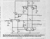
Much more ancient, John Linsley Hood has shown a circuit with a kind of symetrical mirror at the input which can be followed by a differential Vas (a lot lot of forward gain !), but he never used it. Instead, only once, he used a conventional differential pair which each collector was followed by a Vas with a constant current source load. One of the Vas conventionnaly drove the output stage and the other was connected to the inverting input through resistors : this was positive feedback (a principle having some similarities with a Dynaco preamp ?). It was Linsley-Hood's alternative to Hitachi mosfet amp (it's very simple too), intended to have a more stable standing current in the Vas. This is one of the most intriguing amplifier circuit I ever see and, to my knowledge, nobody, even its author, has tried to use it again. I built it, it worked ok from the start, it was very stable (I dismantled it a couple of years later to build the next JLH project, much more conventional, using the same mosfets). One feature from this amp with positive feedback was its offset wich was very low without any triming, around one millivolt. I carefully match the input devices.
~~~~~~~~~ Forr
§§§
"The input stage cann't have a current mirror load, because of the differential VAS"
I think McLaren ampifiers have a current mirror load and a differential Vas. Maybe this circuit is due to Doug Self.
Much more ancient, John Linsley Hood has shown a circuit with a kind of symetrical mirror at the input which can be followed by a differential Vas (a lot lot of forward gain !), but he never used it. Instead, only once, he used a conventional differential pair which each collector was followed by a Vas with a constant current source load. One of the Vas conventionnaly drove the output stage and the other was connected to the inverting input through resistors : this was positive feedback (a principle having some similarities with a Dynaco preamp ?). It was Linsley-Hood's alternative to Hitachi mosfet amp (it's very simple too), intended to have a more stable standing current in the Vas. This is one of the most intriguing amplifier circuit I ever see and, to my knowledge, nobody, even its author, has tried to use it again. I built it, it worked ok from the start, it was very stable (I dismantled it a couple of years later to build the next JLH project, much more conventional, using the same mosfets). One feature from this amp with positive feedback was its offset wich was very low without any triming, around one millivolt. I carefully match the input devices.
~~~~~~~~~ Forr
§§§
Hi forr.
Self was not a fan of the differential vas, so I don't think it can be due to him. I'll look in my JLL Hood books to see if I can find the circuit to which you are referring. Any chance of a picture to show what you mean?
Regarding R9 and bias stability, there is an elegant solution in MikeB's "explendid" symasym amp in this thread . I could kick myself for not thinking of it!
BTW thanks Eva and Bensen for the suggestions.
johnnyx said:
Next I increased the gate stopper resistors to 200 ohms-- no oscillatons.
I'll do this to them all now, I can re-connect the zobel and hopefully the resistors won't burn out again.
Hi Johnnyx,
I'm glad my tip about increasing gate stoppers helped you.
Greetz
Ben
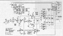
Good for discussion : first Transnova mosfet amp. Positive feedback too, it seems. The accompanying text says that path C creates an infinite "error" gain withtout prõblems of instability. I think a Dynaco tube preamp used such a scheme too.
~~~~~~~ Forr
§§§
~~~~~~~ Forr
§§§
Attachments
JOHNNYX
'Regarding R9 and bias stability, there is an elegant solution in MikeB's "explendid" symasym amp in this thread . I could kick myself for not thinking of it!'
Sorry I didn't find what you exactly mean. The thread is very large. I looked the schematics at post 1. Can you tell me where I should look ?
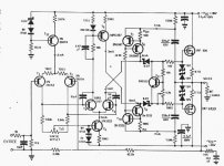
Here's another scheme due to Stocchino wich should do well with Vas current stabilty.
~~~~~~~~ Forr
§§§
'Regarding R9 and bias stability, there is an elegant solution in MikeB's "explendid" symasym amp in this thread . I could kick myself for not thinking of it!'
Sorry I didn't find what you exactly mean. The thread is very large. I looked the schematics at post 1. Can you tell me where I should look ?
Here's another scheme due to Stocchino wich should do well with Vas current stabilty.
~~~~~~~~ Forr
§§§
Attachments
Hi forr
Thanks for the schematics, much clearer now.
The JLL Hood design in post 36 has a current mirror load differential VAS, but the input stage doesn't have a mirror load, it has two resistors. That is what I meant by "the input stage cann't have a mirror load because of the differential VAS". The VAS can have a mirror load, and it does, but not the input stage. I had hoped that there might have been a way that I hadn't thought of.
With R9 and bias stability, the schematic is shown here as an attachment... I didn't realise how long the thread was!
There are similarities between this MOSFET amp and MikeB's amp. The thing I was referring to was the use of a transistor to pass the current to the mirror, instead of a resistor, R9. In this way, the VAS collector is held at 0v, and the current source on the input stage sets up the currents for the whole amp. A very nice solution I think.
Not sure about the other amps using positive feedback, these require some thought.
Attachments
- Status
- This old topic is closed. If you want to reopen this topic, contact a moderator using the "Report Post" button.
- Home
- Amplifiers
- Solid State
- Power Amp Schematic