Hi Forr,
That's very interesting. In one article, the VCE swing is causing the main distortion in VAS transistor (Early effect). So, some are cascoding this transistor to advoid Cbc unlinearities.
I found this here. It is actually an opamp based power amp. Opamp usually handle +/-15V, so to get +/-33V swing, the designer uses bootstrapped common collector with resistor 2k (R4, R5), cap 470uf (C3, C4), and zener (not clear, BZ10V?).
But reading your explenation above, this configuration could have something special.
Example : if the X1 (NE5532) is not opamp, but discrete power amp front end (diff, VAS). If this discrete front end (X1) is powered this way, it will have better PSRR? (No emitor in front end is contacted to high rail supply, which has the ripple).
And have no Early effect, even on VAS transistor? (Constant voltage all the time due to bootstrapping).
The question is, while the front end is powered only from +/-15V (for example), and the output stage have voltage of +/-50V (for example), does this whole system (front end only from +/-15V with help of bootstrapping) can reach output voltage of +/-50V perfectly? Like ordinary 3 stages poweramp where the front end (diff, VAS) is also powered from the high supply rail, not from low rail +/-15V with help of bootstrapping?
If it can reach the output as good as the VAS+diff is powered from high rail (ordinary topology), then it has many advantages, better PSRR and no Cbc unlinearities (even in VAS transistor).
Attachments
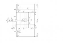
That schematic is not clear, too small. I zoom it, but not clear enough.
Maybe this can help to understand that blurry picture. It is made by Mauropenasa, a little different, but close.
http://www.diyaudio.com/forums/attachment.php?s=&postid=625580&stamp=1114189280
Look at the left schematic (driver). It is based on opamp, from +/-15V, but can swing to +/-33V. In this concept, Mauro didn't use bootstrapped, just voltage divider (R9/R10 + R11/R12)
To help discussing the bootstrapping, imagine Mauro's schematic is replaced with :
-R10+R12=2k
-R9+R11 (originally R=4k7) replace with Z15V+470uf bootstrap cap.
-U2 is not LM318, but discrete front end for something like my description in post #81 (the blurry schematic).
Hi Lumanauw,
I think this circuit cannot drive the MOSFETs beyond the chips own boosted supply which is divided down from the output. If this is so, it cannot achieve R2R as can my Simple Killer Amp topology - within 2V!
Yes it should give good PSRR.
On the subject of bootstrapping (e.g. Simple Killer Amp topology),
I have designed a 'bass extender', a Q=2 HP filter tunable to extend the bass of existing loudspeakers. The power supplies use 2 transistor low noise and bootstrapped design regulators for over 80dB line regulation. Without bootstrapping it's 33dB.
It will be released in 2 weeks.
Cheers,
Greg
Sorry for resurrecting this old thread, but I have just resurrected a couple of the original Maplin amps that I built in 1984 and never got round to using - I've simply replaced the electrolytics and fired them up. I'm running them both off a single +/-50V PSU with 10,000uF on each rail. Yes, I have noticed a slight buzz if I put my ear right next to the speaker. How much of that is down to lack of PSRR and how much is just pickup from the wiring, inadvertent ground loops etc., I don't know. What I don't like the idea of is the two amps interacting, and larger PSU fluctuations bleeding through. The definitive test, perhaps, is to send a signal only to one channel with a dummy load and listen to the other - I won't be able to do it for the next few days, however. Bah!
In the meantime I've done a quick and dirty SPICE simulation - without the precise models for those exact transistors and MOSFETs, but it appears to work more-or-less as expected. Interestingly I found I had to set the output transistor bias 'pot' very much to the far (high resistance) end, which seems to be the case on the real amps - the designer could have drastically reduced the range of that pot.
I don't see a huge amount of PSU breakthrough, with PSRR at 57 dB (assuming I have calculated this correctly! 14mV p-p at the speaker with 10V p-p PSU modulation, or thereabouts). I can't imagine that that would be sufficient to cause an audible buzz when idling..?
I was quite excited to read of the idea of replacing the differential pair bias resistor with a constant current source, assuming that this might improve the PSRR drastically, but it doesn't (in SPICE anyway). 14mV p-p becomes about 10mVp-p. Someone earlier in this thread suggested that a disadvantage of this might also be an audible 'thump' at switch on..?
What does seem to work (in SPICE) is regulating the rails except for the output stage, using 40V zeners and 330R of resistor on each rail on each amp and reducing the differential pair emitter resistor to 39k (I don't know if anyone else has done this for real? Do these values seem about right? Any other component values need changing?) The circuit board appears very easy to modify, just needing to slice two tracks to the MOSFET drains, bypassing each with a stout wire direct to the PSU, and maybe adding some local bypass caps to make up for the ones now separated on the PCB. Still it's a shame to have to bodge the PCB in this way. In SPICE, the 14mVp-p ripple at the speaker reduces to less than 1mV.
If anyone is wondering whether these amps are any good, I've run them very loud indeed and they sound magnificent to me, driving some fairly good speakers. If I hadn't read about the poor PSRR here I would have been perfectly happy with them as they were, but now I'm going to have to rip them apart again! If the single channel dummy load test doesn't reveal anything untoward I'm leaving them as they are, however!
I don't see a huge amount of PSU breakthrough, with PSRR at 57 dB (assuming I have calculated this correctly! 14mV p-p at the speaker with 10V p-p PSU modulation, or thereabouts). I can't imagine that that would be sufficient to cause an audible buzz when idling..?
I designed a similar amplifier and found I had to decouple the output power supply from the driver stage. This got rid of an annoying hum.
I am a fan of the Maplin amps having used their 225WRMS amp on a mobile disco for many years. The MOSFET amp just wasnt loud enough for disco work. The amp was one of my first electronic projects and it worked first time which was very encouraging.
Yes, just did the test with a single channel signal and a 5R dummy load. At an ordinary 'loud' volume there is a very faint breakthrough onto the other channel that disappears when you disconnect the dummy load, almost certainly coming through the shared PSU.
I have some high voltage regulators ready to do the job... but I would bet a million pounds that no one could ever hear it with both speakers connected or hear the faint mains buzz from more than 6 inches away from the speaker... Do I chop up the PCBs and wiring and bodge another little circuit into the box over this..?
I have some high voltage regulators ready to do the job... but I would bet a million pounds that no one could ever hear it with both speakers connected or hear the faint mains buzz from more than 6 inches away from the speaker... Do I chop up the PCBs and wiring and bodge another little circuit into the box over this..?
- Status
- This old topic is closed. If you want to reopen this topic, contact a moderator using the "Report Post" button.
- Home
- Amplifiers
- Solid State
- Power Amp Schematic