The only reason I can think of in why your saying emitter resistance higher means slower speed is that it takes more time for current to travel into next stage.
Because it means higher voltage swing, which has to charge/discharge the internal, and leakage capacitors. I hope You agree that all bjt has internal capacitance.
Sajti
Yes I do agree bjt has internal capacitance.
But lets say the vas of this very fast amp outputs 20v, wouldn't this mean there has to be 20v extra drop of voltage ontop of the idle voltage accross emitter reistance.
I do not think reducing emitter resistance would reduce the ammount of votlage drop required to be developed accross this emitter resistance for 20v out.
I also doo agree that more voltage swing means less speed.
Last edited:
....
Speed of a amp means nothing, human hears up to only 20khz. HI FI is not Raido Frequency going faster means nothing.
Well, I agree and disagree with the statement.
")
If speed of an amp, means signal rise / fall time then Speed of an amp means a lot, and in this case then I would disagree.
And here I agree, altho human hearing can be measured to about 20kHz and not much higher, any decent audio source e.g. vinyl and other well recorded analog sources have frequency components e.g. harmonics that are much higher than 20kHz. These harmonics can be easily precieved by human hearing and are generally described as the brilliance / detail / definition in the audio content since audio signal information is greater at higher frequencies.
For any decent audio amp, it is imperative that the amp can reproduce signals much higher than 20kHz, 200kHz or even up to 300kHz are highly desirable. This is reflected in a sharp signal rise / fall time without much or any over / under swings.
Therefore it is also highly desirable to have speakers that can reproduce well over 20kHz, e.g. ribbon tweeters (50kHz) or diamond dome tweeters (specd. at resonant frequency at 300kHz) come to mind.
Altho, perhaps at 500kHz to 1Mhz (if ever achieved) there is likely not much more gained as far as amplifier distortion performance goes.
Generally, the higher frequencies the amplifier can reproduce, the less distortion this amplifier produces.
I am sure someone would disagree, but for me RF barely starts at about 1MHz.
And, sure there are many other factors influencing distortion, not just frequency response.
I wounder if you can really hear some sort of diffrence, on scope my head amp with input cap can still give out more than 50khz without being able to see by eye that the square wave has a charging up slope caused by input cap.If speed of an amp, means signal rise / fall time then Speed of an amp means a lot,
Also can output upto 2mhz without seeing much distoriton on the square wave. My head amp also uses no fast schematic at all.
(also no overshoting and zero ringing, output excatly same as input)
Personally with very high quality caps, I can't hear sound quality increace when preamp has cap coppled input output but very good schematic.
With comparison to direct input no caps in series fastest speed.
I'd say the signal rise / fall time performance would have to do more with good schematic design rather than schematic design for high freq repoduction.
Hi everyone, I will give it a try explaining the recent discussion on CM (Current Mirror), please correct me if I missed something.
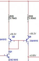
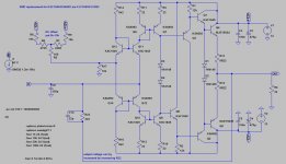
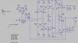
I will use part of the schematics as presented few posts earlier, see attachment.
For a given AC signal fed to a CM with comparatively "large" E resistor (Q8) will increase the voltage modulation Vbc on the out going CM transistor (Q9), hence the Miller capacitance (of Q9) will limit the CM BW more than for a CM with "small" E resistors.
Let's also briefly look a bit what happens to Q1 which is feeding the CM stage (Q8, Q9).
For a given AC signal fed into a CM with comparatively "large" E resistors, the VAC developed over Q8 + R28 will be "larger", and therefore impose an increased Vbc modulation over Q1, hence the BW for Q1 also decreases.
Sure the CM will work with larger E resistors, but it becomes degraded at higher frequencies, and there's a point of diminishing returns.
Attachments
Thats right, to be able to output 20vac there must be 20v developed accross q9, change the emitter reistance to 1R or 1KR same 20v must be dropped accross r30.
EIDT: I am starting to question my self on this
I also doo agree that more voltage swing means less speed.
If the system has high capacitance then no high freqency can be develped regardless of amplitude of the high freq in system.
I don't think more voltage swing can mean less speed.
EIDT: I am starting to question my self on this
I also doo agree that more voltage swing means less speed.
If the system has high capacitance then no high freqency can be develped regardless of amplitude of the high freq in system.
I don't think more voltage swing can mean less speed.
Last edited:
I don't think more voltage swing can mean less speed.
In this case yes. Higher internal resistance, and high voltage swing means less speed. You have to use current gain instead of voltage gain if you want fast amplifier.
Just check the mentioned fast opamps, that they use current mirror without any emitter resistors...
Sajti
I can see where you are comming from now, From basic principles without searching up design of high freq amps.In this case yes. Higher internal resistance, and high voltage swing means less speed. You have to use current gain instead of voltage gain if you want fast amplifier.
Just check the mentioned fast opamps, that they use current mirror without any emitter resistors...
Sajti
Time constant = CR
V=IR
R=V/R
T=CV/R
Higher voltage less speed.
More resistance less speed.
agreed
You said current mirror decrecses the change in voltage of transitors, for static situtation yeah.
But when music playing I'd say no. Because of this
Unless someone can point out I am wrong and this is not the case for the vas.if q9 was to have 20v ac to appear on collector, wouldn't that mean 20v must be added or subtracted on top of the idle voltage of r30.
This 20v will always be develped regardless of resistance size.
The only way for the collector to decrease in 20v is to have 20v drop accross r30
But does charging up internal resistances of transistors have that much of an effect? My point of view is that the diffrence is very small cannot be noticed.
Last edited:
But does charging up internal resistances of transistors have that much of an effect? My point of view is that the diffrence is very small cannot be noticed.
Maybe not, maybe yes. It depending what kind of amplifier You want to build. If You use no feedback, and 20kHz is the maximum You want to reach, this effect is negligible.
But if You use high amount of feedback, than You need high bandwith, because of the pole splitting.
If Your current mirror is part of the VAS, it maybe more important, as the VAS has high gain, and the internal capacitances are subject of the Miller effect.
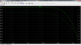
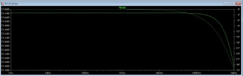
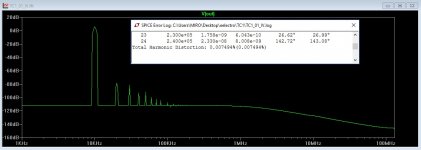
Attached my current amplifiers open loop response.
Sajti
Attachments
DAC I/V
can be used as I/V, for DACs
this is example for 1-1.2mA single output (AD1862, PCM1704, ...)
KSC1845/KSA992 can be replaced by SMD equivalents FJV1845/FJV992
can be used as I/V, for DACs
this is example for 1-1.2mA single output (AD1862, PCM1704, ...)
KSC1845/KSA992 can be replaced by SMD equivalents FJV1845/FJV992
Attachments
can be used as I/V, for DACs
this is example for 1-1.2mA single output (AD1862, PCM1704, ...)
KSC1845/KSA992 can be replaced by SMD equivalents FJV1845/FJV992
Hi,
the 22ohms in the emitter is OK, if You are able to well select the pairs.
The 2SC3324/2SA1312 are better. They are the SMD equivalent of the famous 2SC2240/2SA970, used in many high quality amplifiers...
Sajti
I tested something ... and is working ...
Attachments
-
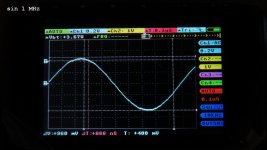 sin_1MHz.jpg354.8 KB · Views: 115
 -
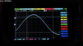 sin_800kHz.jpg345.1 KB · Views: 127
 -
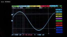 sin_300kHz2.jpg383.1 KB · Views: 151
 -
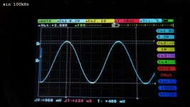 sin_100kHz.jpg377.3 KB · Views: 215
 -
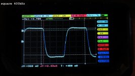 sq_400kHz.jpg351.1 KB · Views: 247
 -
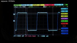 sq_200kHz.jpg370.6 KB · Views: 253
 -
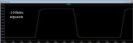
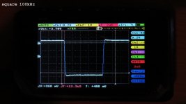 sq_100kHz.jpg336.8 KB · Views: 390
 -
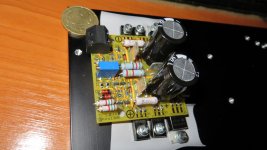 image020.jpg445.6 KB · Views: 559
 -
 TC01_build.jpg119.9 KB · Views: 540
 -
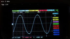 sin_2MHz.jpg371.1 KB · Views: 167
- Status
- This old topic is closed. If you want to reopen this topic, contact a moderator using the "Report Post" button.
- Home
- Amplifiers
- Solid State
- Another very fast CFA concept