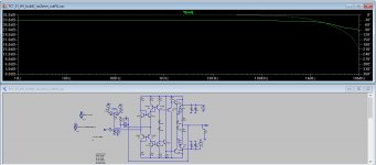
I think you'll have to dig a little more about how CFA is working.I changed these values ... except feedback resistors, because with 500/23 it goes into oscillation
cap in feedback with CFA amp is questionable, you can find right value with square simulation (bad/too big value can increase possibility of oscillation, too small value can do the same, right value can help)
here is ltspice file if you like to simulate ...
You still think VFA ;-)
Of course, your amp will oscillate if you don't set a Miller cap between your output (take your feedback path independently right at the output, just before your Zobel, and your miller cap in this path, between output and the feedback resistance.
The only way to get a CFA rock stable, minimize distortion, and get the best bandwidth.
With CFA, increasing the impedance of the feedback path is a way to decrease the bandwidth, that is, precisely, what we don't want. One of the advantage of the CFA is that closed loop bandwidth and feedback does not vary with the gain.
I explained why in one of my previous posts.
Have a look at the LC posts in the SSA thread, it will help-you to understand better.
I think you'll have to dig a little more about how CFA is working.
You still think VFA ;-)
Of course, your amp will oscillate if you don't set a Miller cap between your output (take your feedback path independently right at the output, just before your Zobel, and your miller cap in this path, between output and the feedback resistance.
The only way to get a CFA rock stable, minimize distortion, and get the best bandwidth.
With CFA, increasing the impedance of the feedback path is a way to decrease the bandwidth, that is, precisely, what we don't want. One of the advantage of the CFA is that closed loop bandwidth and feedback does not vary with the gain.
I explained why in one of my previous posts.
Have a look at the LC posts in the SSA thread, it will help-you to understand better.
I dont know exactly what do you think.
Anyway, I tested this circuit in my way (low-cost), with real results. It is working with my values without oscillations, sound result is perfect.
Noise is below 2mV and can be even better. I will no longer improve this one concept, because other things and concepts to test are on the way.
Anyway, whoever can improve this concept and post own improvements, but most importantly are real tests

It is not "what I think", but a long life of professional design with a particular interest (not exclusive) in commercial CFA amps.I dont know exactly what do you think.
Fell free to try to understand what is said... or not. and benefit ... or not... of other's experiences.
For the moment, i have no time to work on your files, I will try later to give-you practical answers to illustrate what I tried to explain.
With your way to analyze the stability, you are creating a pole (to answer to the Nyquist's requisite) with a bridge made with your (near linear) capacitance and the*non linear* capacitance of the emitter of the input transistor. Is-it more clear ?
Lazy Cat, my friend, or scott wurcer, can you explain-it a better way ?
Last edited:
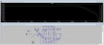
small update: TC_1.0_v2
- version with bigger output transistors 30MHz (FJL4215/FJL4315)
- improvement in few values (resistors for input transistors, VAS resistors)
- PCB remained small, in cheap size 5x5cm (gerbers included)
... sound is excellent
Hi Miro1360, your project is excellent!
I see that it has the potential to be built as a discrete high voltage power opamp. Is it possible to generate PCB with these modification?Six connections in PCB frontside , <Bias>, <-ve_input>, <+ve_input> <Vcc>, <GND> and <Vdd>. One connection <Out> at the backside.
With these modification, one can choose either inverted or non-inverted input, and connects the required bias accordingly.
As I don't know how to generate PCB file myself, your kind help is much appreciated!
PCB based on any version of your circuit are welcome, not necessarily the ccs one. Many thanks,
Sulcorebutia
Attachments
Hi Sulcorebutia, sorry for my late reply but I have not seen your post.
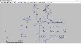
Avoid these CCS. They are working in the simulation but in the real world they are terrible. If you want a CCS, go with the CRD (current regulative diode) or simple a jfet with resistor.
Start with this post: https://www.diyaudio.com/forums/solid-state/312596-fast-cfa-concept-11.html#post5365617
Instead of R14/R16 and R1/R2 a CRD can be used, or jfet+resistor.
Differential inputs should working too (but I have not tried).
Note, that if you want a lot of power (>160W) you should replace KSC3503/KSA1381 with a high power VAS trand. When high power is used, also all protections should be considered.
https://ctrlv.cz/shots/2019/01/15/DIE7.png
Attachments
- Status
- This old topic is closed. If you want to reopen this topic, contact a moderator using the "Report Post" button.