But... most CFA circuits have limited gain to begin with so their ultimate closed-loop THD dips down only so far.
... which is rapidly changing. Witness this new branch on the CFA tree:
Jan
Attachments
It is not hard to get low distortion without a lot of feedback...using current mode topology. About 7-10 years ago I had this power amplifier design was being sold under Monster products brand. And, as you can see the gain was even reduced. it produced about <.01% thd+N at full power output (200W/8) at any freq.
View attachment I-Mode Monster Pwr Amp.pdf
THx-RNMarsh
View attachment I-Mode Monster Pwr Amp.pdf
THx-RNMarsh
Last edited:
Currently, most grounded feedback resistors in audio power amps have values between 100 and 1 kOhm. Are there examples of VFAs with a low impedance inverting input and CFAs with a high impedance inverting input ?I think Bob Cordell's definition of CFA vs VFA is the best one so far, with respect to the impedance looking into the active element tied to the feedback node. It suggests that there can be a transition from CFA to VFA as the element impedance rises, although this is most often set by the circuit design.
It's the core of the rebellion against the CFA concept.Transconductance is a factor for every amplifier circuit as a whole, and for each active device in the circuit - all active devices that can provide "gain" are transconductance devices. However, as these are imperfect man-made things, gm is limited and we see tiny voltage variations at the control pin of the device as current varies through the device. Even were we to run the typical CFA-input at amperes of current, there is still Vbe voltage variation. with signal.
For those who want to see, it should be by now clear why the "CFA" effect is important only for small closed loop gains. The R1||Rf variation is important only when R1 and Rf are close. For large Rf values (that is, large closed loop gains) the open loop inverting input loading is practically R1, which leads to an almost pure VFA behavior when the loop is closed.
Therefore, for any "CFA" topology with a closed loop gain of say 26dB (like very common in audio) the behavior is almost that of a pure VFA amplifier, R1||Rf~R1
I didn't respond to this earlier due to time constraints. While what you write isn't technically false, it is contrived because only a dufus hoping for a relatively constant closed loop bandwidth would attempt to achieve high closed loop gains by using large values for Rf.
I have switch-gain CF amplifiers applied in the field which retain a closed loop bandwidth deviations no more than 20% for closed loop gain variations over two orders of magnitude.
In the ideal case (infinite open loop gain and an input buffer with a perfectly zero output resistance) if Rf is a fixed value and the closed loop gain is set by varying Rg only, then the closed loop bandwidth will not vary.
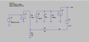
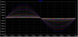
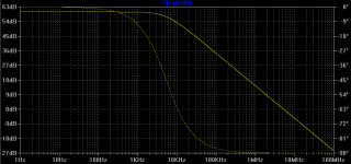
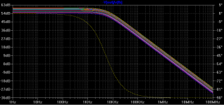
I've attached a simple simulation for demonstration purposes. An idealized CFA is modelled and the closed loop gain is stepped logarithmically from unity to ~100 (a 40 dB range) by varying Rg only (cfa2.png). If the output resistance of the input buffer (Zb) is negligibly low (say 10u) then the closed loop bandwidth essentially does not deviate from 5.3MHz over the full gain range at all (cfa3.png).
Increasing Zb to 10 ohms to demonstrate the effect of a non-ideal buffer, the close loop bandwidth exhibits far less gain independence, but still only varies over a ~2:1 range for the 100:1 variation in range for the closed loop gain (cfa4.png); this is exactly as one would expect as at the highest closed loop gain Zb at 10 ohms essentially = Rf||Rg, effectively halving the transconductance of the input stage. Obviously still a great deal better than a comparative VFA model.
The LTspice *.asc file is also attached for those that would like to play.
Attachments
Last edited:
An idealized CFA is modelled and the closed loop gain is stepped logarithmically from unity to ~100 (a 40 dB range) by varying Rg only (cfa2.png).
A minor correction: make that from 2 to ~100 (a 34 dB range).
Hi
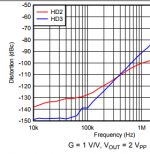
Um... No disrespect to Mr.Marsh - I love everything you write - but I think you also prove my assertion: 70ppm at 1kHz and 120ppm at 20kHz is hardly stellar promotion of CFA; rather, I believe, it demonstrates what the standard configuration is capable of. Maybe it proves Jan Didden's point, too, inasmuch as that is a design from 7-10 years ago and the more "gain-boosted" recent designs of Dadod and others have much lower THD while retaining the CFA core.
Many designs use a combination of VFA and CFA techniques. For example, Bryston's power amps have an overall VFA format and loop values, with NFB applied to BJT bases, while encompassing nested CFA loops in the power section. The basic design has not changed since 1974. Borgioni (spelling) had similar designs prior to this.
Poldaudio: Your analysis is very interesting. I often thought that an "opamp" front end with all of its feedback-might applied to making the feedback node as low-z as possible was something worth trying. Of course, Alexander did just that in several of his designs. But then... for the complexity of, say, a discrete opamp, one could simply scale it up and have it be the power amp as we do anyway.
There was a thread here called "New VAS design", or similar, where it seemed to me a CFA was given a diff-front-end which added a lot of gain to sacrifice and provided easy DC-offset control. The phase-splitting action of the usual diamond front-end was retained but level-shifted to tie directly to the low-voltage diff stage. The level shifting ultimately made the CFA loop unmanageable, but the evolution of the circuit was very interesting and had extreme bandwidth at low-THD at least until an output stage was attached. It just comes to mind, so may not be relevant to the discussion here...
Jan: Where does the graph come from? It seems to represent a preamp rather than a power amp at only 2Vpp?
Hi
Um... No disrespect to Mr.Marsh - I love everything you write - but I think you also prove my assertion: 70ppm at 1kHz and 120ppm at 20kHz is hardly stellar promotion of CFA; rather, I believe, it demonstrates what the standard configuration is capable of. Maybe it proves Jan Didden's point, too, inasmuch as that is a design from 7-10 years ago and the more "gain-boosted" recent designs of Dadod and others have much lower THD while retaining the CFA core.
Jan: Where does the graph come from? It seems to represent a preamp rather than a power amp at only 2Vpp?
I think you missed the detail I pointed out... the amp had deliberately lowered OLG. Do you see how? The two 68K to ground (R54-55)? Normally this would not be limited --- thus much reduced THD+N. Very very good for a simple and 'old' design showing its potential. As you know, I have measured Dadod's CFB amp and it is so low in distortion as to strain the limits of my measuring system (if you get the grounding and shielding right).
As for the 2v -- preamp output distortion- again with simple CFB amp for headphone amp, I can get below the limits of the AP2722 analyzer. 8 transistors. And, Not using a lot of feedback.
On another point... which has been reported on before but again by Waly..... the BW/Gain effect observed with CFB amps only holds for low to moderate gains. This is true. I think, from real circuits of my own is up to about 40dB max.
THx-RNMarsh
Last edited:
Jan: Where does the graph come from? It seems to represent a preamp rather than a power amp at only 2Vpp?
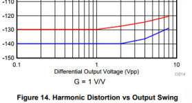
It's one of these new super chips with 0.3A max Iout and 40V supply. I am not at liberty to disclose the type.
Here's another snipped: THD at 100kHz!
It seems safe to say that CFA distortion figures can hold their own, at least, against those of traditional CFA chips.
Jan
Attachments
On another point... which has been reported on before but again by Waly..... the BW/Gain effect observed with CFB amps only holds for low to moderate gains. This is true. I think, from real circuits of my own is up to about 40dB max.
Wally's claim was for very low gains - like less than 10, above which:
"the (CFA) behavior is almost that of a pure VFA amplifier, R1||Rf~R1"
This is only true if you use a fixed value for Rg and vary the gain by increasing the value of Rf, which is a misapplication of feedback for a CF amplifier as increasing the value of Rf effectively over-compensates the amplifier.
It is a different story if you appropriately choose a fixed value for Rf and vary the gain with Rg only. Now as you progressively decrease the value of Rg the effective transconductance of the input stage increases in proportion to the closed loop gain - bingo, constant gain-bandwidth product.
Last edited:
This is only true if you use a fixed value for Rg and vary the gain by increasing the value of Rf, which is a misapplication of feedback for a CF amplifier as increasing the value of Rf effectively over-compensates the amplifier.
It is a different story if you appropriately choose a fixed value for Rf and vary the gain with Rg only.
Exactly. Because Rf sets the BW, you can vary Rg to vary the gain with (almost) no change in BW. This is why almost all CFA datasheets give recommended values for Rf wrt BW, (almost) independent of required gain.
Jan
Wally's claim was for very low gains - like less than 10, above which:
"the (CFA) behavior is almost that of a pure VFA amplifier, R1||Rf~R1"
This is only true if you use a fixed value for Rg and vary the gain by increasing the value of Rf, which is a misapplication of feedback for a CF amplifier as increasing the value of Rf effectively over-compensates the amplifier.
It is a different story if you appropriately choose a fixed value for Rf and vary the gain with Rg only. Now as you progressively decrease the value of Rg the effective transconductance of the input stage increases in proportion to the closed loop gain - bingo, constant gain-bandwidth product.
I see the nonsense keeps flowing. CFA's with multiple mA flowing it the input stage have DC errors that make them fairly useless. Take say 250uA collector current and an optimal 1K feedback resistor at 26dB closed loop gain you are at the roll off of the constant GBW curve. Waly was correct.
BTW Someone send me a pretty complete overview of all the CFA chips out there, including the discontinued ones. Impressive (number of devices as well as specs).
CFB and Transimpedance circuits | Linear Audio NL
Jan
CFB and Transimpedance circuits | Linear Audio NL
Jan
..........Proposed new name........-> Proposed new acronym
An acronym wich has already been proposed defines CFAs as amplifiers having a low impedance inverting input. It is not very expressive.
Much better : recent posts recall that CFAs are amplifiers
- having an Input Stage Transconductance Primarly Set by the Main Feedback Network
(or, otherwise said)
- having an Open Loop Gain Primarily Set by the Main Feedback Network
A smart acronym built from one of these features would certainly make consensus.
Scott not sure I get it. Isn't Rf largely responsible for setting the roll-off and thus BW? Then set Rg to your required gain?
Jan
About 1/2 way down the GBW does not depend solely on Rf at large closed loop gains.
Current Feedback Amplifiers I | Analog Devices
OK, that clears up some things for me, the influence of the non-zero Zout of the buffer, but that is a design variable. The paper talks about 20 - 40 ohms but I have seen 12 ohms or less in some recent devices iirc.
One thing I don't apprecaite is that in this and other papers, it is stated that the feedback drives the error current (in a CFA) or the error voltage (in a VFA) to zero. This is not actually the case; in a CFA the error current is driven to a very precise Vo/Zt (the transimpedance) or, in a VFA, to Vo/Ao.
This is significant in some measurement methods that attemp to identify output non-linearity by examining the input error voltage or current. A guy like Gerald Graeme (remember him?) did some interesting work on that.
Jan
Well, as long as Jan has to repeat the need of an non zero error in the feedback to have something to amplifyFeedback by current in the input stage provided by feedback by voltage from output stage, what else to discuss? I use such feedback from 1970'Th; later John Curl and Dmitry called my example as "Arrogant". Before this topic have started, however...
Show must go on?
,yesOne thing I don't apprecaite is that in this and other papers, it is stated that the feedback drives the error current (in a CFA) or the error voltage (in a VFA) to zero. This is not actually the case; in a CFA the error current is driven to a very precise Vo/Zt (the transimpedance) or, in a VFA, to Vo/Ao.

Mona
Hi
Did you measure the amp without those limiting components to see how much performance was being sacrificed?
Yes, that is what I referred to as a modern gain-boosted CFA. Its THD is down in the single-ppm range, which is more state-of-the-art today.
The current AP is around 2ppm as a limit, although there is an new package coming out that will be better. It's not a problem to get sub-ppm for small-signal, and even "all-zeroes" in LTspice which is <10ppb. This is what i consider true state-of-the-art. Once you see those six zeroes you are spoiled for life... hehe For power amps, I'm a bit disappointed with 10ppm or higher at 20kHz and full output and none of the circuits I've been trying (mostly VFA) have even as much open-loop gain as one of Self's but the THD20 is far lower.
Do you believe that the open-loop circuitry of the standard CFA is more linear than that of a typical VFA? If it is, then that might allow for less gain overall to achieve a given THD level.
I think you missed the detail I pointed out... the amp had deliberately lowered OLG. Do you see how? The two 68K to ground (R54-55)? Normally this would not be limited --- thus much reduced THD+N. Very very good for a simple and 'old' design showing its potential.
Did you measure the amp without those limiting components to see how much performance was being sacrificed?
IAs you know, I have measured Dadod's CFB amp and it is so low in distortion as to strain the limits of my measuring system (if you get the grounding and shielding right).
Yes, that is what I referred to as a modern gain-boosted CFA. Its THD is down in the single-ppm range, which is more state-of-the-art today.
IAs for the 2v -- preamp output distortion- again with simple CFB amp for headphone amp, I can get below the limits of the AP2722 analyzer. 8 transistors. And, Not using a lot of feedback.
The current AP is around 2ppm as a limit, although there is an new package coming out that will be better. It's not a problem to get sub-ppm for small-signal, and even "all-zeroes" in LTspice which is <10ppb. This is what i consider true state-of-the-art. Once you see those six zeroes you are spoiled for life... hehe For power amps, I'm a bit disappointed with 10ppm or higher at 20kHz and full output and none of the circuits I've been trying (mostly VFA) have even as much open-loop gain as one of Self's but the THD20 is far lower.
IOn another point... which has been reported on before but again by Waly..... the BW/Gain effect observed with CFB amps only holds for low to moderate gains. This is true. I think, from real circuits of my own is up to about 40dB max.
THx-RNMarsh
Do you believe that the open-loop circuitry of the standard CFA is more linear than that of a typical VFA? If it is, then that might allow for less gain overall to achieve a given THD level.
that in this and other papers, it is stated that the feedback drives the error current (in a CFA) or the error voltage (in a VFA) to zero. This is not actually the case; in a CFA the error current is driven to a very precise Vo/Zt (the transimpedance) or, in a VFA, to Vo/Ao.
This is significant in some measurement methods that attemp to identify output non-linearity by examining the input error voltage or current. A guy like Gerald Graeme (remember him?) did some interesting work on that.
Jan
It makes sense as either an ideal limiting case or as a first approximation. You normally want the open-loop transimpedance, transadmittance, voltage gain and current gain to be as high as possible to make the error terms as small as possible; let the transimpedance, transadmittance, voltage gain and current gain approach infinity and you get a nullor. If you are interested in the precise value of the error, you can't approximate it as zero of course.
- Home
- Amplifiers
- Solid State
- Current Feedback Amplifiers, not only a semantic problem?