The current mirror does not belong to the input stage.
It is only a load for the current output by the input stage in most CF-opamps, but it is absolutely not mandatory.
It is your opinion.
The base is the non-inverting input.
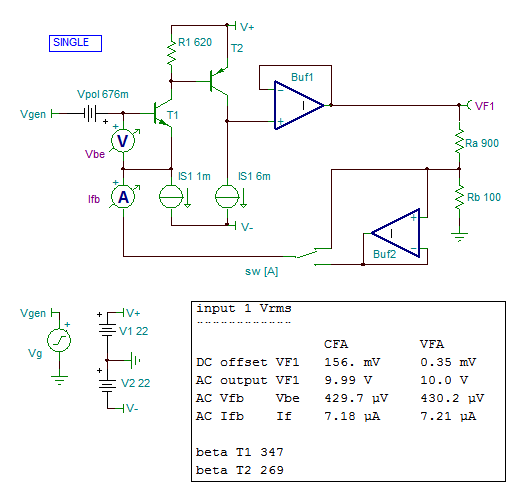
This emitter is the inverting input which receives the feedback signal, not the signal of the source.
Simulation shows that buffering the signal from the feedback network, just like it happens with a long tail pair input stage, makes the circuit an indisputable VFA. You can see that it has very little effects on the current and the voltage involved in the feedback signals around the device in charge of the subtraction process.
To summarize, a VFA tends to look like a buffered CFA, if we admit that these acronyms have any meaning.
[LURK MODE=OFF]
Hello there from "down under".
I'm having a bit of difficulty following the discussion here and I acknowledge in advance that my interjection after 30-plus pages of argumentation is likely pointless!
Consider a "CFA" opamp IC that is stable with a 900R Rf and a 100R Ri, returning a closed loop gain of 10 (1+Rf/Ri).
Now change Rf to 9k and Ri to 1k. What has happened? The closed loop gain is still 10. The magnitude of voltage fed-back to the low-impedance inverting input is still exactly the same, but something dramatic has in fact happened. By a (simplified) 1st order approximation the closed loop bandwidth has decreased by a factor of 10.
This is because the the current conveyed via the inverting input to the compensation capacitance has been reduced by the same factor. The equations given in any in-depth introductory text to the CFA topology make this fundamental property plain.
[LURK MODE=ON]
The non-inverting input of a VFA has a high impedance.
The non-inverting input of a CFA has a high impedance.
The inverting input of a VFA has a high impedance.
The inverting input of a CFA has a low impedance so it is often considered as current input rather than a voltage input.
With the adjuvant of some extra circuitry to the concerned devices, these impedances can be made almost infinite for all the non-inverting inputs or almost null for the inverting output of the CFA.
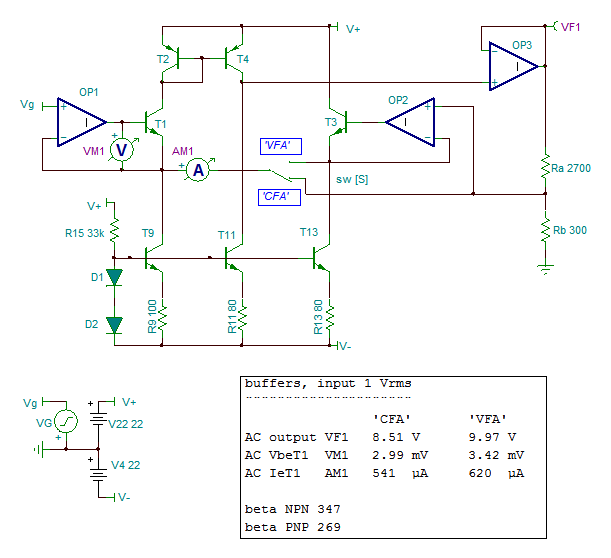
The extra circuit can consist in the introduction of a local negative feedback circuit including the input devices. It is an op-amp on my simulation of today.
Compared with my yesterday schematics, the buffer of the feedback divider in the VFA configuration has now a transistor which makes familiar the look of the whole amplifier as it has a real differential input stage now.
Comments on voltage and current differences between the configurations and their names are wellcome.
The non-inverting input of a CFA has a high impedance.
The inverting input of a VFA has a high impedance.
The inverting input of a CFA has a low impedance so it is often considered as current input rather than a voltage input.
With the adjuvant of some extra circuitry to the concerned devices, these impedances can be made almost infinite for all the non-inverting inputs or almost null for the inverting output of the CFA.
The extra circuit can consist in the introduction of a local negative feedback circuit including the input devices. It is an op-amp on my simulation of today.
Compared with my yesterday schematics, the buffer of the feedback divider in the VFA configuration has now a transistor which makes familiar the look of the whole amplifier as it has a real differential input stage now.
Comments on voltage and current differences between the configurations and their names are wellcome.
Attachments
Last edited:
[LURK MODE=OFF]Consider a "CFA" opamp IC that is stable with a 900R Rf and a 100R Ri, returning a closed loop gain of 10 (1+Rf/Ri).
Now change Rf to 9k and Ri to 1k. What has happened? The closed loop gain is still 10. The magnitude of voltage fed-back to the low-impedance inverting input is still exactly the same, but something dramatic has in fact happened.
True. What happened is that the open loop amplifier gain and bandwidth changed by changing the feedback network. The feedback network loading effect at the inverting input did this, not the feedback type itself. Once again, it's a particular circuit topology property, nothing to do with the feedback type or ratio.
When analyzing a shunt (output) series (input) feedback type, you have to consider the inverting input loaded by R1||Rf and the output loaded by R1+Rf (this one can usually be ignored). In the "CFA" particular circuit topology, the open loop gain and bandwidth are affected by this R1||Rf but, to the CFA fan club exasperation, the open loop Gain*Bandwidth product is still constant, like in any good old VFA.
For those who want to see, it should be by now clear why the "CFA" effect is important only for small closed loop gains. The R1||Rf variation is important only when R1 and Rf are close. For large Rf values (that is, large closed loop gains) the open loop inverting input loading is practically R1, which leads to an almost pure VFA behavior when the loop is closed.
Therefore, for any "CFA" topology with a closed loop gain of say 26dB (like very common in audio) the behavior is almost that of a pure VFA amplifier, R1||Rf~R1
forr,
I am still struggling: You modify a circuit in which one of the defining characteristics is a low impedance input current port fed usually by a suitably scaled (low value) resistor and then claim that the new circuit proves CFA=VFA. Is that not like saying John wears a red shirt; Jack puts on a red shirt therefore Jack is John?
Take a look here http://www.ti.com/lit/an/sloa021a/sloa021a.pdf
Sims don't lie.
No, people lie, in particular when they have a vested interest.
Do you have any examples?
People that are quoting a chart that is illegible and that do not explicitly show the supporting data.
Plus that I guess you missed my post here: http://www.diyaudio.com/forums/soli...dback-amplifiers-semantic-26.html#post5161768
"People that are quoting a chart that is illegible and that do not explicitly show the supporting data."
Which chart?
"Plus that I guess you missed my post here: Current Feedback Amplifiers, not only a semantic problem ? "
Which simulations? Any simulation is exactly that - a simulation - and is designed to explore circuit behaviour. I would think it only becomes 'toxic' when people either don't build the right circuit to prove or disprove their point, or as in the case elsewhere, refuse to accept any point of view that is contrary to theirs. This then is no longer about engineering but about belief systems. Truly pseudo science.
Of course, you could always ask the author of the simulation circuit to share their file with you.
Have you noticed that there are two configurations on my schematics ?forr,I am still struggling: You modify a circuit in which one of the defining characteristics is a low impedance input current port fed usually by a suitably scaled (low value) resistor.
One of them is the purest CFA you can imagine, as its inverting input has a null impedance, null impedance on which rely the reasonnings of CFA with diamond input stage which have certainly not a null impedance, less than 50 Ohm says Texas Instruments
No such claims because they are full circuits, A meaning Amplifiers.then claim that the new circuit proves CFA=VFA.
My investigation is only concentrated on the feedback subtraction process, which is similar in both configurations and manages with voltages only (possibly issued from currents across impedances).
It is obviously not clear to every body that I am not treating differences between CFAs and VFAs which are complete circuits.
Thank you. Please do not think I lack documentation. May I add that the ideas I defend are not mine at all and were already discussed more thirty five years ago.Take a look herePHP:[URL]http://www.ti.com/lit/an/sloa021a/sloa021a.pdf[/URL]
Last edited:
Any simulation is exactly that - a simulation - and is designed to explore circuit behaviour. I would think it only becomes 'toxic' when people either don't build the right circuit to prove or disprove their point, or as in the case elsewhere, refuse to accept any point of view that is contrary to theirs. This then is no longer about engineering but about belief systems. Truly pseudo science.
Got it, so simulations are never wrong, and if you have some simulation results you no longer need a brain to cross check, validate and interpret the results. Your problems with elementary logic transcend the lack of basic EE understanding.
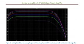
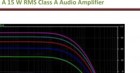
Point in case, the chart in your sx amp description on your web site, which is illegible, and does not have anyway enough data to support your statement. The closed loop bandwidth do vary over that closed loop range (18-26dB), and would be even more to 30dB (not shown) but check the same in the 6-10dB closed loop gain. There, it is indeed invariant. Please plot the 3dB closed loop bandwidth vs. the closed loop gain, and check out how it converges toward the VFA 6dB/octave behavior (or CLG*BW=constant) as the closed loop gain increases.
This thing becomes as boring as the Bybee devices.
The BW at 40.7 dB gain is 358 kHz and at 11.6 dB 548 kHz. At 30 dB is 446 kHz.
This amplifier is clearly not constant GBW over the typical audio application gains.
The chart in the write up is perfectly legible - your monitor is the issue, or zoom inf you are using a iPad - the numbers are there.
Please note the chart title: Figure 2 - sx-Amp Simulated Frequency Response. Closed loop bandwidth remains essentially constant even though the closed loop gain is changed from 18 dB to 26 dB, a feature of the CFA topology.
The BW at 40.7 dB gain is 358 kHz and at 11.6 dB 548 kHz. At 30 dB is 446 kHz.
This amplifier is clearly not constant GBW over the typical audio application gains.
The chart in the write up is perfectly legible - your monitor is the issue, or zoom inf you are using a iPad - the numbers are there.
Please note the chart title: Figure 2 - sx-Amp Simulated Frequency Response. Closed loop bandwidth remains essentially constant even though the closed loop gain is changed from 18 dB to 26 dB, a feature of the CFA topology.
I suppose we could not agree even on the color of the sky. A little free advertising:
Attachments
Waly, show us some of you work i.e. amps, schematics, builds etc.
Thanks
I don't feel like. There!
P.S. Ok, here: My amp revisited
Schematic is of no interest here, it employs a total of about 80 bipolar transistors (including the 8 pairs of output devices) per channel. I have no plans to build this, it was only a curiosity driven "because I can" demo. There's simply no good reason to invest money in such a construction, as long as it doesn't and won't sound better than my salvaged (10 quid @ flea market) HK amplifier.
Last edited:
Got it, so simulations are never wrong, and if you have some simulation results you no longer need a brain to cross check, validate and interpret the results. Your problems with elementary logic transcend the lack of basic EE understanding.
Point in case, the chart in your sx amp description on your web site, which is illegible, and does not have anyway enough data to support your statement. The closed loop bandwidth do vary over that closed loop range (18-26dB), and would be even more to 30dB (not shown) but check the same in the 6-10dB closed loop gain. There, it is indeed invariant. Please plot the 3dB closed loop bandwidth vs. the closed loop gain, and check out how it converges toward the VFA 6dB/octave behavior (or CLG*BW=constant) as the closed loop gain increases.
This thing becomes as boring as the Bybee devices.
Another day, another insult.
Well, like it or not CFA's are here to stay in audio and there's squat any detractors can do about it.
Well, like it or not CFA's are here to stay in audio and there's squat any detractors can do about it.
Sure. Happy sales!
I don't feel like. There!
P.S. Ok, here: My amp revisited
Schematic is of no interest here, it employs a total of about 80 bipolar transistors (including the 8 pairs of output devices) per channel. I have no plans to build this, it was only a curiosity driven "because I can" demo. There's simply no good reason to invest money in such a construction, as long as it doesn't and won't sound better than my salvaged (10 quid @ flea market) HK amplifier.
I think the lack of a schematic and the refusal to put one up speaks volumes.
(I had 11 IC designers in my team at one stage. Smart guys, but absolutely incapable of stepping out of their bubble except for one guy who after 5 or 6 very successful years left and went into project management and ended up running a team of 200 design/test/integration engineers on SOIC's. $200 million dev budget at the time. He was smart and related well to people - MSc grad. Get some mentoring - you need it
")
Have you noticed that there are two configurations on my schematics ?
One of them is the purest CFA you can imagine, as its inverting input has a null impedance, null impedance on which rely the reasonnings of CFA with diamond input stage which have certainly not a null impedance, less than 50 Ohm says Texas Instruments
No such claims because they are full circuits, A meaning Amplifiers.
My investigation is only concentrated on the feedback subtraction process, which is similar in both configurations and manages with voltages only (possibly issued from currents across impedances).
It is obviously not clear to every body that I am not treating differences between CFAs and VFAs which are complete circuits.
Thank you. Please do not think I lack documentation. May I add that the ideas I defend are not mine at all and were already discussed more thirty five years ago.
Ok. Clear
- Home
- Amplifiers
- Solid State
- Current Feedback Amplifiers, not only a semantic problem?