Thinking feedbackOverreact? You make it sound as if the feedback thinks about what it does.
Jan
 , perhaps, i think so i am.Suppose you can't invert that
 No, i mean if the input changes very rapidely and the output is following (delayed) the feedback has to be adjusted to have the right amplitude to be substracted from the input.
Mona
When CFA is ideal, had infinite flat frequency response and infinite gain, inverting input sees zero ohm load on a feedback divider. If it's gain is limited, it sees feedback resistor's resistance divided by gain with feedback divider's resistance in parallel, i.e. some feedback by current due to this resistance. But with increase of frequency this load impedance becomes complex, and works like a frequency compensation of parasitic inertion of charges and parasitic capacitances that increases stability on higher frequencies.
Feedback is not as simple as Scott and Jan want to portray.
Yes, the error signal is present at the input almost instantly, because the difference is generated by the INPUT and the OUTPUT, through a normally resistive network that is almost instantaneous, BUT the input stage has to respond by over-driving with a much greater current than low frequency steady state or DC would in order to overcome the low open loop bandwidth to make it correspond to the closed loop bandwidth that the feedback loop creates. It is in the over-driving current that the extra distortion is generated, leading to TIM and PIM distortion.
Yes, the error signal is present at the input almost instantly, because the difference is generated by the INPUT and the OUTPUT, through a normally resistive network that is almost instantaneous, BUT the input stage has to respond by over-driving with a much greater current than low frequency steady state or DC would in order to overcome the low open loop bandwidth to make it correspond to the closed loop bandwidth that the feedback loop creates. It is in the over-driving current that the extra distortion is generated, leading to TIM and PIM distortion.
...BUT the input stage has to respond by over-driving with a much greater current than low frequency steady state or DC would in order to overcome the low open loop bandwidth to make it correspond to the closed loop bandwidth that the feedback loop creates. It is in the over-driving current that the extra distortion is generated, leading to TIM and PIM distortion.
That is a classic case of how an amplifier has dynamic distortions. And the fix is contained within: 1) bandlimit the driving signal so that the amplifier is not asked to make fast transitions, and 2) use high standing currents so that the current response to a transient is only a fraction of the normal standing current.
It's not so much about dominant pole compensation - as long as the stages can linearly drive the compensation components (rule #2 above) then using a LF dominant pole is not inherently a recipe for disaster. If you want the highest linearity, it's nice to have enough loop feedback. But, it's also nice to have loop feedback around fundamentally linear stages, which favors more local feedback. Where that bar is moved - from local to loop feedback - is just a tradeoff, and as long as the amp is fast enough to stay linear, disaster will not happen at either end of the tuning range.
I think the most fruitful avenue is to use techniques to make stages more linear without excessively degenerating their gain, and then wrap them within sensible loop feedback. As long as the stages are fast enough, more loop feedback is generally better.
When CFA is ideal, had infinite flat frequency response and infinite gain, inverting input sees zero ohm load on a feedback divider. If it's gain is limited, it sees feedback resistor's resistance divided by gain with feedback divider's resistance in parallel, i.e. some feedback by current due to this resistance. But with increase of frequency this load impedance becomes complex, and works like a frequency compensation of parasitic inertion of charges and parasitic capacitances that increases stability on higher frequencies.
Here is simplified mechanism of frequency compensation in CFA due to local feedback by current in the 1'St stage, and impedance of a global feedback loop.
Attachments
![Screenshot-LTspice XVII - [Draft2.asc].png](/community/data/attachments/585/585829-4aa79e8da96e1cac66e4c105783686f0.jpg)
When I was at the electronics research lab of the Delft University of Technology in the early to mid 1990's, they only used the term current feedback or its Dutch equivalent stroomtegenkoppeling when talking about amplifiers with a low-impedance current input and a high-impedance current output. Later, when I got interested in historical electronics, I learned that historically, the term was also used for amplifiers with series feedback at both the input and the output, like what you described.
I have my doubts that these terms were ever universally applied with the rigour that some are imagining.
Anyway, there are more terms like this: in 2015, after using computers for decades, I finally learned that in its original meaning a computer is a human being.
Those computers were for the most part almost exclusively boobs-equipped too (just in keeping with a prior theme).
Overreact? You make it sound as if the feedback thinks about what it does.
If there is phase shift, the feedback is no longer exactly 'negative' (in opposite phase). If the phase accumulates 180 degrees extra, you have now positive feedback - the stuff oscillators are made of.
But before that point you start to see ringing and prolonged settling time of course.
All in most good feedback and control systems books.
Jan
Except that any good feedback and control systems book will explain that a feedback circuit with a loop gain greater than unity at a frequency with 180 degrees or more extra phase shift can still be stable, just as long as the Nyquist stability criterion is met. This is used extensively in sigma-delta modulators and class-D amplifiers nowadays.
Thinking feedback
No, i mean if the input changes very rapidely and the output is following (delayed) the feedback has to be adjusted to have the right amplitude to be substracted from the input.
Mona
If you mean that you need frequency compensation and that feedback is less effective for fast signals than for slow signals, then you are absolutely right.
Feedback is not as simple as Scott and Jan want to portray.
Yes, the error signal is present at the input almost instantly, because the difference is generated by the INPUT and the OUTPUT, through a normally resistive network that is almost instantaneous, BUT the input stage has to respond by over-driving with a much greater current than low frequency steady state or DC would in order to overcome the low open loop bandwidth to make it correspond to the closed loop bandwidth that the feedback loop creates. It is in the over-driving current that the extra distortion is generated, leading to TIM and PIM distortion.
This is such BS, it isn't even wrong. If you have an amp that exhibits this behavior it is a spectecular example of incompetent design. Surely not one of yours, I hope?
Jan
What's wrong with John Curl's post? Is it the term over-driving? Maybe John interprets this as driving harder than at very low frequencies, while Jan and Bonsai associate it with first-stage clipping, a.k.a. slewing.
It is true that the first stage has to deliver a larger output signal for frequencies above the open-loop bandwidth than for very low frequencies, and that this leads to an increase of its distortion compared to very low frequencies. In a well-designed feedback amplifier the first stage is designed to handle this without distorting excessively and without getting anywhere near clipping.
It is true that the first stage has to deliver a larger output signal for frequencies above the open-loop bandwidth than for very low frequencies, and that this leads to an increase of its distortion compared to very low frequencies. In a well-designed feedback amplifier the first stage is designed to handle this without distorting excessively and without getting anywhere near clipping.
YES !

..........Info/book on CFA have been around a long time.....
Thx-Richard Marsh
Currently many interpretations of the CFA topology rely on the two following schematics extracted from figures #1 and #3 of S. Franco's article :
In defense of the current-feedback amplifier | EDN
The first one represents a classical CFA circuit built around a diamond current-conveyor stage (Q1 to Q9) and a diamond buffer output (Q11 to Q14).
The Vn point, the common point to the output of the currents mirrors (if accessible) and the Vo node can source and sink currents.
The current-conveyor action consists in duplicating the current in the Vn node at the output side of the current mirrors.
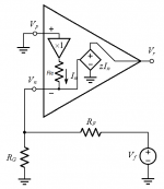
The second schematics is a simplified application of the CFA.
The Vp node is grounded (0V) and the Vn point is connected to the output of a divider (Rf, Rg). The divider input is not connected to the buffer output of the CFA but to a voltage generator.
The Vn node which offers a quite close copy of voltage at Vp which is at 0V can be seen as a virtual earth.
One proof invoqued for the validity of the CFA concept is that, as there is 0V across Rg, Rf and Rg does not constitute a voltage divider and the only value to take in account is the current through Rf.
Of course ! As it is, the circuit offers a virtual earth input without global negative feedback. It Rg is connected to another voltage source instead of ground, some current will pass through it and enter the Vn node where it is added (mixed) with the current coming from Rf.
But, we have not to forget that the virtual earth input without global negative feedback, albeit being quite well performing, if far from perfection.
Now, let's reconnect Rg to ground, keep voltage Vf genrator as it is, and change the Vp connection from ground to an other voltage generator. What happens ?
In defense of the current-feedback amplifier | EDN
The first one represents a classical CFA circuit built around a diamond current-conveyor stage (Q1 to Q9) and a diamond buffer output (Q11 to Q14).
The Vn point, the common point to the output of the currents mirrors (if accessible) and the Vo node can source and sink currents.
The current-conveyor action consists in duplicating the current in the Vn node at the output side of the current mirrors.
An externally hosted image should be here but it was not working when we last tested it.
The second schematics is a simplified application of the CFA.
The Vp node is grounded (0V) and the Vn point is connected to the output of a divider (Rf, Rg). The divider input is not connected to the buffer output of the CFA but to a voltage generator.
An externally hosted image should be here but it was not working when we last tested it.
The Vn node which offers a quite close copy of voltage at Vp which is at 0V can be seen as a virtual earth.
One proof invoqued for the validity of the CFA concept is that, as there is 0V across Rg, Rf and Rg does not constitute a voltage divider and the only value to take in account is the current through Rf.
Of course ! As it is, the circuit offers a virtual earth input without global negative feedback. It Rg is connected to another voltage source instead of ground, some current will pass through it and enter the Vn node where it is added (mixed) with the current coming from Rf.
But, we have not to forget that the virtual earth input without global negative feedback, albeit being quite well performing, if far from perfection.
Now, let's reconnect Rg to ground, keep voltage Vf genrator as it is, and change the Vp connection from ground to an other voltage generator. What happens ?
Last edited:
As long as the controlled source is current controlled, why would there be no feedback without re? Of course the schematic with controlled source is an oversimplification, but if you would have an ideal current controlled voltage source with high transimpedance at your disposal, I don't see why you would need an re.
More thoughts
Note : here I implicitly use the singular to refer to a pair of transistors of the inverting input (in-) of a diamond circuit.
The in- of a CFA behaves as a voltage follower (100 % local feedback) and acts firstly as an output towards the feedback divider.
It is the feedback network which is the load of the inverting input and not the divider output which loads the inverting input.
Thus the values of the network resistors do not much affect the voltage at in- which can have an almost null impedance (however, these values lower the open loop gain when they are increased) .
The in- delivers the necessary current to impose on its load a voltage which is a copy of the non-inverting (in+) voltage (buffers of a diamond circuit are considered as perfec).
This current is the feedback current in the CFA (topology) term.
But the feedback in amplifying circuits consists of substracting the return voltage from the input voltage. Currently, we only have a current...
Happily, the above process of delivering current is under the control of the transconductance of the transistor which emitter forms the inv- node and which can be seen as a kind of local output.
The transconductance is the law which intimately correlates the base-emitter voltage (Vbe) of a bipolar transistor and the current through it.
Here the base receives the (buufered) input voltage, and the emitter a voltage in correlation with the feedback current.
The Vbe, correlated to the feedback current, executes the fundamental process of voltages subtraction in an indisputable manner.
When the feedback is disconnected from the output, the inverting input is loaded only by Rb. When the feedback is re-established, the resistive value seen by in- increases and the current it delivers decreases.
The higher is the feedback signal, the lower is the error signal.
*
The intial question was
Current Feedback Amplifiers, not only a semantic problem ?
It is established that in a CFA topology :
- the feedback process is done in the voltage domain
- a current tied to the feedback process exists but is transposed to a voltage.
To make this transposition clearly explicit, a world or a term is painfully lacking in the expression 'Current Feedback Amplifier'.
If one is found and approved, both the semantic and technical problems raised in this thread will be solved.
More thoughts
To make this transposition clearly explicit, a world or a term is painfully lacking in the expression 'Current Feedback Amplifier'.
If one is found and approved, both the semantic and technical problems raised in this thread will be solved.
Propose something and I/we can use it here and maybe start a trend .....
CFVA ?
and for the other -- VFVA
THx-RNMarsh
Last edited:
One of the sonic virtues of passive RIAA comes from the fact that we do Not have different amounts of NFB at various frequencies. With active Riaa you do have different amounts of NFB at different frequencies.
If you remember audio review of phono preamps, they always characterized the sound into the sound of the bass, mid and highs as having separate qualities. Unknowingly, much along the lines of the RiAA filter inflection points.
With passive RIAA, the amps Neg-FB is same all over the BW for a consistant sound quality.
That is why I used passive RIAA in my phono preamp in 1977-80. It is another example of how careful listening can influence designs.
When I stopped using LP as music source, I gave that preamp to Kavi Alexander (Water Lily) who later told me he really liked it.
THx-RNMarsh
Last edited:
- Home
- Amplifiers
- Solid State
- Current Feedback Amplifiers, not only a semantic problem?