") ) but not Rx'ed yet. I am home only on weekends so I may not be the best guy to get you timely feedback.
) but not Rx'ed yet. I am home only on weekends so I may not be the best guy to get you timely feedback.BrianGT PSU boards
Are there any dangers or downfalls to mounting capacitors on both sides of the PSU boards? I am thinking if I "doubled" caps and put 3x2 on top and 2x2 on bottom I could fit 10 x 10000uf caps per board. It would be a heck of a lot cheaper than putting 6 15000uf on top.
Thanks,
Brad
Are there any dangers or downfalls to mounting capacitors on both sides of the PSU boards? I am thinking if I "doubled" caps and put 3x2 on top and 2x2 on bottom I could fit 10 x 10000uf caps per board. It would be a heck of a lot cheaper than putting 6 15000uf on top.
Thanks,
Brad
pinkmouse said:How would you solder them?
And there is the catch! I guess it would be quite impossible to solder. It's always the obvious answers that elude me.
BTW - I like the new Avatar
Gentlemen-
When ever you have a chance please just inspect the contents against what ever BOM you have and let me know if I missed anything. You don't actually have to assemble them.
NOTE to ALL:
I included a 250 VAC 400 VDC Wima cap to put across the primaries as a noise filter. It is NOT on the BOM but I had them so I threw it in. Use it if you like, if not, save it for something else.
buglehead said:Rabstg,
Did you end up with any leftover kits? How much did they wind up costing? I have Al's boards.
Thanks,
Joe E.
I don't mean to be rude, but I'm not even addressing that until everyone who had ordered has rx'ed and accepted their kits.
They have waited WAY too long and I do not have the time to handle new kits until the old ones or out and done.
Ask again in a couple of weeks when they have all been sent. I am holding off on sending the out of country(ooc) kits until we have positive verification that they are correct. Shipping is out of my pocket and I do NOT want to ship twice ooc since it is much more expensive.
Ok guys, I know I made you all wait 'cos I took so long perfecting the boards.
But it's not really fair to make all the other members who paid for parts kits outside the US wait because you can't be bothered to check them. Come on, give Troy a break, after all the effort he's put into this, all it takes is five minutes of your time to check a list, then everyone else can get a chance to enjoy the sound like Mark and I have been doing.
But it's not really fair to make all the other members who paid for parts kits outside the US wait because you can't be bothered to check them. Come on, give Troy a break, after all the effort he's put into this, all it takes is five minutes of your time to check a list, then everyone else can get a chance to enjoy the sound like Mark and I have been doing.
Andrew-
Thanks for the concern, but I'm in for about 30% of the cost of these kits.
To state a different way, I covered(subsidized) a third of the cost for each channel sold.
The funds for shipping (Not envelopes) have been used on parts quite a while ago.
I ask nothing in return except that all GB'ers be patient with me.
EDIT:
Oh yeah I forgot to mention the contents of the kits went from "main boards only" to "all inclusive EXCEPT output transistors" at no price increase.
Hook-Up
I've populated my boards (PinkMouse), assembled most of my hardware, and am ready to begin assembly and wiring the components. I have some very basic questions regarding the assembly. I'm using 'Dual-Mono' with separate transformers, rectifiers, and caps. Keep in mind, I am a structural engineer with limited background in electronics.....so some of this may seem very obvious.....but I want to be safe.
1. I haven't decided whether to use BrianGT power supplies, or separate rectifiers and smoothing caps. The caps I would use are three or four 22000uf 100v caps from K-Amps per transformer/rectifier. My transformers are 28v+28v at 500VA. Any suggestions regarding resistors across the rails for a CCCR, CRCC, or some similar configuration? Is something like 3kR at 5 watts appropriate? I'm also planning to place an LED and RLED across the rails on each channel's power supply.
2. I know there have been some discussions regarding powering the main board separate from the driver board for power saving, and for possible use of a regulated supply at the main board, but is it okay to simply wire them both directly to the output from the power supply....full voltage?
3. I do not see a direct connection to the output boards from the power supply? Is it correct that all of their power comes from the driver boards?
4. Which pads on the output boards are connected to the D+ (or D-) and FB outputs from the driver boards?
5. Which pads on the output boards provide output to the + and - speaker binding posts?
Thanks for any suggestions, Robert
An externally hosted image should be here but it was not working when we last tested it.
An externally hosted image should be here but it was not working when we last tested it.
Re: Hook-Up
Let me take a crack at #1 and #2-
#1- I would think that 0.2 ohms to 0.5 ohms at 10-25 Watts is what you will want to use for an R with a CRC type filter. The R does not go across a cap but between one cap and the next cap... but you know this.
#2- yes, its ok to wire them all up to the output of the main PS, that is the way I have mine. The purpose of the 27volt zeners is to bring this down on the main board to 27 volts no matter how much higher (within reason) your PS goes.
If you put an LED across the caps to bleed out the voltage when they are turned off, make sure to put a resistor in series with the LED or you led will last about 5 minutes. Edit- is that what you meant by Rled?
Hey, nice pictures. Good luck with this
rjkdivin said:
1. I haven't decided whether to use BrianGT power supplies, or separate rectifiers and smoothing caps. The caps I would use are three or four 22000uf 100v caps from K-Amps per transformer/rectifier. My transformers are 28v+28v at 500VA. Any suggestions regarding resistors across the rails for a CCCR, CRCC, or some similar configuration? Is something like 3kR at 5 watts appropriate? I'm also planning to place an LED and RLED across the rails on each channel's power supply.
2. I know there have been some discussions regarding powering the main board separate from the driver board for power saving, and for possible use of a regulated supply at the main board, but is it okay to simply wire them both directly to the output from the power supply....full voltage?
Let me take a crack at #1 and #2-
#1- I would think that 0.2 ohms to 0.5 ohms at 10-25 Watts is what you will want to use for an R with a CRC type filter. The R does not go across a cap but between one cap and the next cap... but you know this.
#2- yes, its ok to wire them all up to the output of the main PS, that is the way I have mine. The purpose of the 27volt zeners is to bring this down on the main board to 27 volts no matter how much higher (within reason) your PS goes.
If you put an LED across the caps to bleed out the voltage when they are turned off, make sure to put a resistor in series with the LED or you led will last about 5 minutes. Edit- is that what you meant by Rled?
Hey, nice pictures. Good luck with this
Also while placing an LED on one side of the supply, try and place one of equal value on the other polarity as well otherwise one LED on one rail will discharge the supply in a lopsided manner and the amp can go into oscillations while powering down (if no relay is used). While it may not damage the amp, it will cause annoying buzzing sounds from the speakers...
K, not quite so critical, but it all helps. I certainly will be.
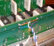
4)D+ Goes to Drive+, and D- goes to Drive -, FB runs back from the positive output post of the speaker terminals, or from the point indicated below
.
5) For the speaker output from the boards, connect a thick wire between the thick top traces on the PCB opposite the devices between the two boards, then from the centre, take off the cable to the positive binding post. The negative post goes directly back to the star ground point.
The pic below shows the principle, but note that I have yet to attach the speaker output cable, the one you can see is the feedback.
Attachments
- Home
- Amplifiers
- Solid State
- Krell KSA 50 PCB