Detached PS
I've seen big class A amps with detached power supplies so its not a problem. Even got an issue of AudioXpress and there was one in there (a few months back).
I think what people are saying is to put a few big caps in your monoblock that doesn't have the PS in it.
That way if there is a voltage drop due to the wire you have created a CRC filter and you will have less ripple and hum. Could even be better than an all-in-one monoblock.
Hi Googler,
I would leave out the R and keep the r in the cable.
I would also fit more C beside the amps (VERY close by) and less beside the rectifier.
I would aim for r = 0r1 to 0r2 each of the flow & return. Choose your lengths and cable gauge to match this. This gives a RC time constant =6.8mS (0r1 + 68mF) The bigger this is the better (100Hz @-3db =1.6mS)
Remember to keep your central star ground BESIDE the amp.
AndrewT said:Hi Googler,
I would leave out the R and keep the r in the cable.
I would also fit more C beside the amps (VERY close by) and less beside the rectifier.
I would aim for r = 0r1 to 0r2 each of the flow & return. Choose your lengths and cable gauge to match this. This gives a RC time constant =6.8mS (0r1 + 68mF) The bigger this is the better (100Hz @-3db =1.6mS)
Remember to keep your central star ground BESIDE the amp.
Thanks Andrew!
So per rail: rectifier side something like 2x10,000uf caps, then cable, and then a 3x10,000uf on amp side?
So if each chassis (PSU, Mono, Mono) has a star ground, should I connect all three of the chassis' star grounds to the one safety ground on the IEC inlet?
googler said:
So if each chassis (PSU, Mono, Mono) has a star ground, should I connect all three of the chassis' star grounds to the one safety ground on the IEC inlet?
People will disagree about this, but that is the way I would do it. Some like to use CL-60's or resistors to connect star ground to saftey ground but some do not. Unless you have ground loops or noise saftey says direct connect like you have proposed.
pinkmouse said:Chassis teaser shot...
Looks like the framing of a Hot Rod to me.
(Al, i miss your familiar avatar, this one looks like a rodent with hemoroid problems)
Re: Re: Par Metal
Case1
Case2
Case3
Case4
Here are some front, side, and rear shots of the bare case. The top, not pictured, is not vented. Also, I will probably fabricate some heavier handles to better represent the massive Krell 'feel', but these are the biggest handles Par-Metal offers.K-amps said:
Can you post frontal and side pics?
Case1
Case2
Case3
Case4
jacco vermeulen said:Looks like the framing of a Hot Rod to me.
Well, the Krell is certainly hot!
")
(Al, i miss your familiar avatar, this one looks like a rodent with hemoroid problems)
Sorry Jacco, but the old one is gone forever. I like this new one, it squeeks when you hurl it at the wall...
Yes....I was planning to make rectangular cut-outs for the mounting of the output boards and Q111 (probably the whole driver board) as soon as I know exactly where I am going to mount them. I wanted to be sure I understood the wiring of all the components first.lgreen said:Nice case! Steel is a horrible conductor of heat, so you will want to put a cut-out or holes in the case side for mounting the transistors directly to those swweeeet looking heatsinks.
Re: Re: Re: Par Metal
Have you looked at the 65xx series handles? (I love Par metals enclosures)
http://www.par-metal.com/60s04.gif
http://www.par-metal.com/60series.htm
rjkdivin said:
.... Also, I will probably fabricate some heavier handles to better represent the massive Krell 'feel', but these are the biggest handles Par-Metal offers......
Have you looked at the 65xx series handles? (I love Par metals enclosures)
http://www.par-metal.com/60s04.gif
http://www.par-metal.com/60series.htm
Re: Re: Re: Re: Par Metal
I had never noticed their 65 series before....those would be good, and would certainly have the massive feel of the original Krell handles. I was thinking of somthing a little more rectangular like the the originals though.
Robert
Thanks Troy,rabstg said:
Have you looked at the 65xx series handles? (I love Par metals enclosures)
http://www.par-metal.com/60s04.gif
http://www.par-metal.com/60series.htm
I had never noticed their 65 series before....those would be good, and would certainly have the massive feel of the original Krell handles. I was thinking of somthing a little more rectangular like the the originals though.
Robert
Mains Safety
Hi Googler,
I have never used a separate Mains powered PSU and low voltage (DC) powered amplifier, nor have I seen any safety recommendations for this arrangment.
I would like to suggest that the safety ground (mains earth) is only required for the metal casing of the mains powered equipment, i.e. your PSU with first stage smoothing.
I will go further and suggest that the low voltage equipment do not need safety grounds since they never have mains voltages in them. HOWEVER, you must be able to quarantee by design and layout that mains voltage can NEVER pass down the connecting umbilical even if the PSU develops a fault.
If you can meet this stringent safety condition, then the only reason you might want to connect the amplifier cases to the Central Star Grounds (CSG) is to mimic a Faraday cage to reduce the amount of interference leaking into your amplifier circuits. The cases could be connected by a parallel combination of resistor and capacitor to the CSG or by a dead short or even a switch to allow a bit of experimentation.
If you feel you need the extra safety grounds because you cannot design in that earlier safety guarantee then you MUST directly connect the amplifier cases back to the mains safety earth, either through the PSU (preferable) or straight to mains. There must be NO risk of disconnecting the safety ground while the amp is still connected to the PSU. When connected by this method I would recommend that you do not connect the case to the CSG except by a current reducing link i.e. reistor and/or capacitor and/or diode pair and/or switch. These components are there to help prevent mains hum and buzz components leaking into the audio circuits.
Can you experts out there comment on the SAFETY issuses raised in both the senarios proposed in the above paragraphs?
Hi Googler,
re your CrC PSU.
Yes, you have interpreted my suggestion correctly.
Since the general recommendation for the KSA50 Klone is a minimum of 47mF smoothing then it is my opinion that the last stage of smoothing should have this amount of capacitance irrespective of how much first stage capacitance is fitted upstream of the r (cable).
On that basis you are a little shy. This may not matter since you are close and since your extra filter stage will make a reduction in the amount of hum leaking through to the amp. But bass slam may be affected and this is one of KSAs advantages and you should not lightly throw this away for the sake of 4 or 8 capacitors.
Since you are aiming for a lowish final C then I would recommend that you raise r to about 0.2 to 0.4 ohms to get that RC significantly above 1.6mS to get the benefit of the -6db slope above the roll off frequency of your lopass filter. If you do increase the resistance then it becomes more important to maintain a higher level of second stage smoothing. This will also reduce your Vrail potential and give a slight reduction in output power. Effectively insignificant, but worth mentioning before you start measuring actual voltages.
After I wrote my first PSU suggestion it occurred to me that the DC gound (common) from the amp to the PSU might benefit from being half the resistance of the DC flow and return to the Vrails.
Are you aware of PSUD2, the PSU analysis freeware?
Finally, are you planning two rectifiers and two sets of first stage smoothing in the PSU box or just one rectifier and one set of first stage smoothing running to the dual monoblocks located remotely. I would use the first topology but at a cost of more capacitance.
Any comments?
pinkmouse said:
""" it squeeks when you hurl it at the wall."""..
perfect for working on switchmode psu!!!!!!
allan
Re: Detached PS
I already wondered why it has that angry look.
lgreen said:I've seen big class A amps with detached power supplies
it squeeks when you hurl it at the wall...
I already wondered why it has that angry look.
Attachments
Re: Re: Detached PS
Can you say "Speakon connectors and 4 con 10 ga. wire" for the umbilicals?
Would be VERY neat and be able to use the same PSU for my Krell AND Aleph Mina-A / 30......
jacco vermeulen said:Photo....
Can you say "Speakon connectors and 4 con 10 ga. wire" for the umbilicals?
Would be VERY neat and be able to use the same PSU for my Krell AND Aleph Mina-A / 30......
rabstg said:Can you say "Speakon connectors and 4 con 10 ga. wire" for the umbilicals?
Yep.
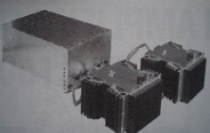
Unless you can get your hands on Camac style connectors like i used for the design on the picture i posted.(see Mark Levinson or Fischer, my audio friend talked me into buying that filthy Swiss stuff)
(which is a fully regulated Class A, the picture does not do justice to the size of such an amplifier)
I used Neutriks on BrianGT's GCs, decoupling a powersupply so easy can be pretty handy.
Re: Detached PS
Thanks Andrew!
I thought the originals had 80,000uf per channel. Wouldn't 50,000uf per rail be 100,000uf a channel?
I just downloaded it, thanks for the suggestion. It looks pretty straight forward. Haven't had a chance to get all my numbers into it yet tho.
I had planned to use a 2 rectifiers (mur2020R) and 2 C for each rail in the PSU box. Separate PSU boards per monoblock.
Thanks for the suggestion Troy. I take it Nuetrik is the brand of choice or are the generics on ebay sufficient?
~Brad
Thanks Andrew!
AndrewT said:
But bass slam may be affected and this is one of KSAs advantages and you should not lightly throw this away for the sake of 4 or 8 capacitors.
I thought the originals had 80,000uf per channel. Wouldn't 50,000uf per rail be 100,000uf a channel?
Are you aware of PSUD2, the PSU analysis freeware?
I just downloaded it, thanks for the suggestion. It looks pretty straight forward. Haven't had a chance to get all my numbers into it yet tho.
Finally, are you planning two rectifiers and two sets of first stage smoothing in the PSU box or just one rectifier and one set of first stage smoothing running to the dual monoblocks located remotely.
I had planned to use a 2 rectifiers (mur2020R) and 2 C for each rail in the PSU box. Separate PSU boards per monoblock.
rabstg said:
Can you say "Speakon connectors and 4 con 10 ga. wire" for the umbilicals?
Thanks for the suggestion Troy. I take it Nuetrik is the brand of choice or are the generics on ebay sufficient?
~Brad
- Home
- Amplifiers
- Solid State
- Krell KSA 50 PCB