Hook-Up
Thanks for the suggestions!
A couple of follow-ups:
1. If you run power directly to the output boards, what pads does it go to?
2. What is the purpose of the feedback from the positive speaker post to the FB point on the driver boards?
3. In your output board picture (Al), what are the purple and blue wires for, and where do they go to? Are these the D+ (or D-) connections to the driver boards?
K-Amps,
The case in my photo is a custom size from Par-Metals....I can look up the order number if you are interested. The sinks I got from a guy on ebay who salvaged them from some micro-wave amplifiers.
Troy,
Thanks for all your work on the kits. I haven't received mine yet but I just wanted you to know that I would be happy to cover any of your out of pocket expenses above what I paid. I am sure that others feel the same way. Please let us know and I'll be happy to paypal my share right over.
Philip
Thanks for all your work on the kits. I haven't received mine yet but I just wanted you to know that I would be happy to cover any of your out of pocket expenses above what I paid. I am sure that others feel the same way. Please let us know and I'll be happy to paypal my share right over.
Philip
RJK
You must know what the BCE of whatever output tranny your using
Example
21194 is a NPN with C to your + rail and E to + spkr. post
21193 is a PNP with C to your - rail and E to + spkr. post
3281A is a NPN #1pin=B #2=C #3=E
1302A is a PNP ditto
Go to Delta Audio and look at the schematic and study it for awhile, and it should come into focus
The + spkr output - both Emitters,feedback, and + spk terminal all tie together with FB going to the tie point on the board
If your feedback wire is close to any stray currents or long, you might use a shielded wire with the ground shield grounded at one end only and the other end open
Someone correct me if I made an error
David
pinkmouse said:
The pic below shows the principle, but note that I have yet to attach the speaker output cable, the one you can see is the feedback.
Is this a preview of the "newbie how-to page"?

~Brad - a newbie in waiting
googler said:s this a preview of the "newbie how-to page"?
Sort of, only hopefully with in focus pics!
RJK;
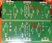
1) The power connections go to the big copper plane, as indicated below, positive to the Drive+ board, negaitve to the Drive- board.
2) The feedback connection acts as a control loop, to get the input and output matching as close as possible. A more technical explanation would take quite a long post...
3) Blue and purple are indeed the driver wires.
David's suggestions are spot on, if you look at the schematic it will all make sense, (hopefully!
).Attachments
Re: tracker-
Troy,
You mean the Wiki link on my signature? (GeWa thanks again!)
lgreen said:once everyone gets their parts, dont forget to update the "krell-o-tracker" with your amp on the wiki, even if its only "in progress."
K-amps, you got that link?
Troy,
You mean the Wiki link on my signature?
(GeWa thanks again!)Re: Hook-Up
Yes please. If not too pricey
rjkdivin said:Thanks for the suggestions!
K-Amps,
The case in my photo is a custom size from Par-Metals....I can look up the order number if you are interested. The sinks I got from a guy on ebay who salvaged them from some micro-wave amplifiers.
Yes please. If not too pricey
Re: Re: tracker-
In the words of a younger Eddie Murphy... "Hey. Wasn't me...."
K-amps said:
Troy,
You mean the Wiki link on my signature?
In the words of a younger Eddie Murphy... "Hey. Wasn't me...."
 .
. Par Metal
ParMetal gave it a part number of '16-19167BPM-Body 14" Wide'. It has a 1/8" anodized front and painted steel chassis. I actually sent them a copy of their catalog page with my desired dimensions superimposed on it....they came up with the model number.
The cost was $125.00 plus shipping with a couple of other smaller cases I ordered. For an anodized aluminum chassis instead of painted steel, they quoted me an additional $25.00.
Thanks Al, David, and everyone else for your help with the wiring details. As I said, my training is not in electronics, but I really enjoy it.
Robert
The case I ordered from Par Metal is a custom size to allow for 2 1/2" sinks on each side. The faceplate is 19" x 7". The chassis is 16" deep x 14"wide x 7" tall.K-amps said:Robert,
Where did you get that chassis/ sinks? Very NICE.
K-
ParMetal gave it a part number of '16-19167BPM-Body 14" Wide'. It has a 1/8" anodized front and painted steel chassis. I actually sent them a copy of their catalog page with my desired dimensions superimposed on it....they came up with the model number.
The cost was $125.00 plus shipping with a couple of other smaller cases I ordered. For an anodized aluminum chassis instead of painted steel, they quoted me an additional $25.00.
Thanks Al, David, and everyone else for your help with the wiring details. As I said, my training is not in electronics, but I really enjoy it.
Robert
An externally hosted image should be here but it was not working when we last tested it.
Re: Par Metal
Can you post frontal and side pics?
rjkdivin said:
The case I ordered from Par Metal is a custom size to allow for 2 1/2" sinks on each side. The faceplate is 19" x 7". The chassis is 16" deep x 14"wide x 7" tall.
ParMetal gave it a part number of '16-19167BPM-Body 14" Wide'. It has a 1/8" anodized front and painted steel chassis. I actually sent them a copy of their catalog page with my desired dimensions superimposed on it....they came up with the model number.
The cost was $125.00 plus shipping with a couple of other smaller cases I ordered. For an anodized aluminum chassis instead of painted steel, they quoted me an additional $25.00.
Thanks Al, David, and everyone else for your help with the wiring details. As I said, my training is not in electronics, but I really enjoy it.
Robert
An externally hosted image should be here but it was not working when we last tested it.
Can you post frontal and side pics?
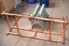
Mark A. Gulbrandsen said:P...are you making a statement?
A statement - just think exoskeleton...
Either way its a lot of nice copper that you better coat with lacquer so it doesn't turn black....
Still pondering the final finish, I might go verdegris.
Got my transformer!
I just bought a 2KVA transformer with 4x28V secondaries from audiohobby.com for $85.
I am considering using this as single supply for both channels, but am also wanting monoblocks for more passive heatsink surface area. I've seen a few commercial systems where the power supply was in a separate box (i.e. Linn). Just wondering, how long can the cord from the PSU to the boards be before bad things (if any) happen?
Thanks,
Brad
The main problem is the long cables increasing the impedance of the PSU. If you put the caps in with the monoblocks, then it's less of a problem, but as it's relatively low voltage, I'd still go with thick, (2.5mm2 minimum), cable, and as short a run as you can get away with...
K-amps said:Yeah! Consider the cable as the "R" in your CRC design.
The secondary idle current is a little hot (29.6V), would any losses be negligable over say a 1 meter run from the transformer/caps to the main/driver/output boards?
How much of a difference would it make to have the PSU boards in the monoblocks vs in the transformer box?
~Brad
- Home
- Amplifiers
- Solid State
- Krell KSA 50 PCB