@Mark, it measures the voltage across the ballast resistors, the average voltage there is not representing the bias, only a microscopic amount of time this voltage represents the bias current (see post #13). The question remains, how to measure this 'moment'. And is it possible to see a simplified schematic of that.
I need to mentioned that I have been researching this (on line) for quite some time now, and I can/could not find any (schematics, ideas or patents). So if you know any references I would be real happy.
I need to mentioned that I have been researching this (on line) for quite some time now, and I can/could not find any (schematics, ideas or patents). So if you know any references I would be real happy.
") , it's there, so we can measure it (see post #13) the question is how? and how simple?
, it's there, so we can measure it (see post #13) the question is how? and how simple?Using optocuplers across the emitter/source resistors seems like a pretty standard way to do this - a number of designs on the pass labs section have it, and you can see a simple schematic implementation here: https://www.firstwatt.com/pdf/art_zen_ ga10jt12.pdf
Cheers,
Cheers,
the D.Self auto bias works while the amplifier output current stays below the ClassA limit.
If a transient takes the instantaneous peak current above the ClassA limit, the stage transitions into ClassB (not the D.Self classB)
the total voltage across the upper and lower resistors does not equate to the required bias voltage while in this high output current mode.
Could one sample the bias voltage quickly and detect the voltage at the instant of the zero current crossing (different from the zero voltage crossing) and use that to reset the bias voltage to that required for the next halfwave cycle?
@AndrewT, probably an S&H may work, but would need a lot of control logic and high-speed circuitry (for zero crossing detection) and an LM339 (for instance) would be to slow (I think). Even so, a analog method would be preferred, the question is still for a simple (DC) method (or maybe not so simple, but not overly complex) that someone did publish or patent or has drawn a schematic for (simplified or not).
@kasey197, using opto couplers will isolate and thus drop ground reference, no DC measurement (or absolute value measurement) would then be possible (at least for any reasonable circuit I think). And the same problem exists, the measured voltage across the ballast resistors give no solution for measuring bias without complex timing circuitry.
@Osvaldo, see post #19, isolation is a problem, no DC results are possible except with lots of additional circuitry. Instead of speculating how it may be solved, do you (any one) have documentation, sample(s), link(s) and other information about any one that ever actually did (of did try) do it.
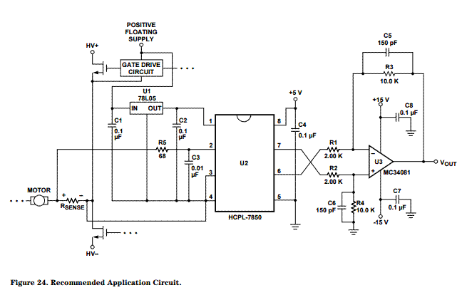
In post #19 appears a different opto from the mine suggested, check again HCPL7850, it has both inputs and outputs isolated up to several KV's, and different returns, and it passes DC currents. Once again, I saw it in the output sensing of poweful AC/AC converters, using the proper shunt in the primary side.
in ClassAB the currents passing through the emitter resistors vary a lot from the bias current that is set up for zero output.The current through the source resistor drives the opto,
Therein lies the problem: monitoring the emitter resistor currents does not relate in any way to the bias current/voltage when there is an output signal that is higher than the ClassA limit for the stage.
@Osvaldo, Post #19 shows an 'effective' simulation using a 'voltage dependent voltage source' with capacitors for insulation and a 480k resistor replacing the HP's input resistance. The result shown is what an 'ideal' HCPL7850 would show you. All other problems (like AndrewT below mentions) still exist.
I think D.Self's trimodal is shown on his public website.
You would be allowed to copy and post for educational purposes. And it gives D.Self free advertising.
If the auto bias is only shown in his Power Amplifier books, then it's a case of asking if you can post a pic, or extract from the pic here.
I don't see a problem since it is for educational use by Members of the Forum. Non Members can't see attached pics.
Last edited:
Sorry, I don't see in the data sheets that any isolation cap is needed.
Only replace emitter resistor by the sensing resistor or add it in series, as in the pic below.
This is a part of Joaquín Sabina's song:

Respectfully, it appears that you don't let us help easily, guy‼
Only replace emitter resistor by the sensing resistor or add it in series, as in the pic below.
This is a part of Joaquín Sabina's song:
Respectfully, it appears that you don't let us help easily, guy‼
Attachments

post19 showing the nearly sinusoidal bias voltage does not confirm that ClassA works correctly.
The average of that non sinusoidal is probably not a good approximation of the true quiescent bias.
But for ClassA an exact bias voltage is not required. as long as it's big enough to stay in ClassA for all intended ClassA output currents.
Is there a way to look at the non sinusoidal error?
That method could be used to then look at the error introduced when currents exceed the ClassA limit.
I have a sneaky suspicion that here we are 70years into solid state output stages and no one has an auto bias system for ClassAB, that has been copied by everyone who cares, because it is difficult .
Last edited:
- Status
- This old topic is closed. If you want to reopen this topic, contact a moderator using the "Report Post" button.
- Home
- Amplifiers
- Solid State
- Measure DC-bias in a operating class AB (or A) amplifier