Q: Is there a simple (or even not so simple) method/circuit available/published to measure the DC-bias of an operating class AB (or A) amplifier.
The intention of the measurement is to create an automated bias adjustment that needs no manual setting of the bias.
Also one could create an measurement device to check bias, under load, in a operating amplifier.
In both cases it would be needed to measure the absolute value of the bias current with an reasonable accuracy.
Edit: Please show a [simple] schematic of your solution")
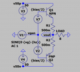
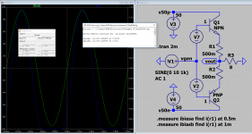
Edit: See post #13, I would like to be able to make a measurement of the DC bias in this amplifier (in any state of operation) [the answer would tell me 182mA see simulation result]
Edit: How to build such an device, and if not possible then 'why not'.
Edit: I am looking for a known/documented method/device/patent to measure DC bias in a operating/functioning amplifier at any level and frequency. Any hint at an idea/patent or otherwise will be appreciated.
Possible solutions,
#101 Jan Didden
#107 Elvee
#117 Ketje
#124, 125 and 126 FdW
#159 FdW
Post #150 http://www.diyaudio.com/forums/soli...rating-class-ab-amplifier-15.html#post5099448 Reactive load sample.
Post #159 http://www.diyaudio.com/forums/soli...rating-class-ab-amplifier-16.html#post5100000 Completed version (V1).
Post #164 http://www.diyaudio.com/forums/soli...rating-class-ab-amplifier-17.html#post5100044 INA testing for GBW.
Post #171 http://www.diyaudio.com/forums/soli...rating-class-ab-amplifier-18.html#post5100092 DUT-output-offset simulations.
Post #172 http://www.diyaudio.com/forums/soli...rating-class-ab-amplifier-18.html#post5100112 Actually measuring current at current-zero-crossing.
Post #174 http://www.diyaudio.com/forums/soli...rating-class-ab-amplifier-18.html#post5100228 Compare INA's including AD8421.
Post #177 http://www.diyaudio.com/forums/soli...rating-class-ab-amplifier-18.html#post5100251 Measurement results using AD8421.
Post #181 http://www.diyaudio.com/forums/soli...rating-class-ab-amplifier-19.html#post5100930 Resistor tolerances.
Post #191 http://www.diyaudio.com/forums/soli...rating-class-ab-amplifier-20.html#post5101247 Unbalanced ballast resistors.
Post #215 http://www.diyaudio.com/forums/soli...rating-class-ab-amplifier-22.html#post5104638 Possible[2nd time] final version
Post #219 http://www.diyaudio.com/forums/soli...rating-class-ab-amplifier-22.html#post5105034 Updated PDF.
Post #220 http://www.diyaudio.com/forums/soli...rating-class-ab-amplifier-22.html#post5105247 Method Ketje simulation.
Post #238 http://www.diyaudio.com/forums/soli...rating-class-ab-amplifier-24.html#post5222647 BOM with part numbers no order numbers.
The intention of the measurement is to create an automated bias adjustment that needs no manual setting of the bias.
Also one could create an measurement device to check bias, under load, in a operating amplifier.
In both cases it would be needed to measure the absolute value of the bias current with an reasonable accuracy.
Edit: Please show a [simple] schematic of your solution
Edit: See post #13, I would like to be able to make a measurement of the DC bias in this amplifier (in any state of operation) [the answer would tell me 182mA see simulation result]
Edit: How to build such an device, and if not possible then 'why not'.
Edit: I am looking for a known/documented method/device/patent to measure DC bias in a operating/functioning amplifier at any level and frequency. Any hint at an idea/patent or otherwise will be appreciated.
Possible solutions,
#101 Jan Didden
#107 Elvee
#117 Ketje
#124, 125 and 126 FdW
#159 FdW
Post #150 http://www.diyaudio.com/forums/soli...rating-class-ab-amplifier-15.html#post5099448 Reactive load sample.
Post #159 http://www.diyaudio.com/forums/soli...rating-class-ab-amplifier-16.html#post5100000 Completed version (V1).
Post #164 http://www.diyaudio.com/forums/soli...rating-class-ab-amplifier-17.html#post5100044 INA testing for GBW.
Post #171 http://www.diyaudio.com/forums/soli...rating-class-ab-amplifier-18.html#post5100092 DUT-output-offset simulations.
Post #172 http://www.diyaudio.com/forums/soli...rating-class-ab-amplifier-18.html#post5100112 Actually measuring current at current-zero-crossing.
Post #174 http://www.diyaudio.com/forums/soli...rating-class-ab-amplifier-18.html#post5100228 Compare INA's including AD8421.
Post #177 http://www.diyaudio.com/forums/soli...rating-class-ab-amplifier-18.html#post5100251 Measurement results using AD8421.
Post #181 http://www.diyaudio.com/forums/soli...rating-class-ab-amplifier-19.html#post5100930 Resistor tolerances.
Post #191 http://www.diyaudio.com/forums/soli...rating-class-ab-amplifier-20.html#post5101247 Unbalanced ballast resistors.
Post #215 http://www.diyaudio.com/forums/soli...rating-class-ab-amplifier-22.html#post5104638 Possible[2nd time] final version
Post #219 http://www.diyaudio.com/forums/soli...rating-class-ab-amplifier-22.html#post5105034 Updated PDF.
Post #220 http://www.diyaudio.com/forums/soli...rating-class-ab-amplifier-22.html#post5105247 Method Ketje simulation.
Post #238 http://www.diyaudio.com/forums/soli...rating-class-ab-amplifier-24.html#post5222647 BOM with part numbers no order numbers.
Last edited:
Don't know if this is any help but in some ancient Krells from last century, there used to be an optocoupler comparator circuit detecting four levels of bias and a micro determining the best bias level (sustained plateau). Today it should be trivial for a micro to monitor continuous real time bias. Unless, for some reason you don't want to use a micro.
Bias current or bias voltages?
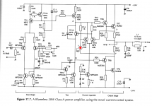
There are some DC servos elsewhere in this page.
Bias current in the emitter/source ballast resistors. I will draw and show an example circuit.
Don't know if this is any help but in some ancient Krells from last century, there used to be an optocoupler comparator circuit detecting four levels of bias and a micro determining the best bias level (sustained plateau). Today it should be trivial for a micro to monitor continuous real time bias. Unless, for some reason you don't want to use a micro.
First of all, it is not that easy, and secondly a micro will find a difficult (if not impossible) task [except when given a lot of support electronics and the micro is running at a high clock rate].
Secondly, I would not like to see a micro in the same environment as the analog electronics.
Depending on current and voltages levels, a simple BJT can do the job, but you can complicate it as much as you want.
Are you near Maastricht? I saw the Andre Rieu video some weeks ago, and appears to be a beautiful place.
My home to Maastricht, about 200kM (I'm near Gouda/Rotterdam).
Can you show some schematic? (simplified to the max
)
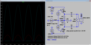
This bug measures a current, and gives an analog replica of it isolated, nowadays used in some AC/AC frequency (for AC motor) converters.
HCPL-7850 pdf, HCPL-7850 Descripcion, HCPL-7850 datasheets, HCPL-7850 Vista ::: ALLDATASHEET :::
Take a look.
HCPL-7850 pdf, HCPL-7850 Descripcion, HCPL-7850 datasheets, HCPL-7850 Vista ::: ALLDATASHEET :::
Take a look.
I can not see (see #13) how this http://www.mouser.com/ds/2/678/V02-3479EN-DS-HCPL-7850-01Oct20120-909312.pdf gets the bias measured.
And more than 100 Euro's is a bit prohibitive (for most amplifiers)
And more than 100 Euro's is a bit prohibitive (for most amplifiers)
Last edited:
- Status
- This old topic is closed. If you want to reopen this topic, contact a moderator using the "Report Post" button.
- Home
- Amplifiers
- Solid State
- Measure DC-bias in a operating class AB (or A) amplifier