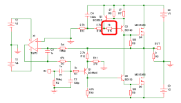
Unity gain CFP in the feedback path can automagically cancel DC offset.
May look like LTP, but actually not. CFP'd feedback has overwhelmingly
more transconductance than the input transistor, but at only unity gain.
So, a deliberately unbalanced (except for DC offset) pair. Remains JLH
style single ended feedback gain path (without the JLH DC problem)...
Might also now technically fall into the category of folded cascodes?
Both DC offsetting transistors also forced equal collector current and
voltage, with no precise adjustments needed to make them equal.
No caps involved this way, maybe no thumps? Theoretically... Possibly...
Well, there's still a big cap in my bootstrap path, so maybe not...
I call this style a shunt tail pair. Could be made a balanced shunt tail,
but in this case works better (prevents loss of 1/2 loop gain) and fewer
parts to leave it very simple and AC gains extremely unbalanced...
Don't mind the current steering and CFP MOSFETs in this drawing.
BJT's as you might normally use for JLH still work. R3 & R13 would
be about 330R if all BJTs were to be used.
The proposed shunt tail offset fix and shunt reg'd bias of SR-JLH2011
is one less transistor than JLH2005's series reg'd currents for similar
and/or superior functions! Shunt reg'd output classes are easily flexed.
No problem to rig a front panel switch with many options...
Enriched A, Linear A, Square Law A, AB + CCS, all easily defined.
And furthermore: Does not care if output transistors match...
All this, ONE LESS TRANSISTOR than 2005 version. Count em'...
Shunt regulated current sources is the magic.
Attachments
Last edited:
Amplifier is running fine at stable 1.5A bias. Turn on is silent. But a loud transient at turn off. What is causing this? Help please.
I suspect it's because of the servo and the fact the amp is single ended. I'm surprised switch on is silent though tbh.
As the rails finally collapse the output will swing over to one or other rail as the servo becomes unable to maintain biasing. There are time constants involved too.
Just thinking out loud but I see you eliminated the "feedback return electroylitic " making the whole amp DC coupled apart from the input coupling cap. I tried to do this on my amp (which is a very similar topoloy) but found the compromises in doing that and still being able to get the DC biasing and wanted AC peformance unacceptable. And I use a 6 second speaker delay on power up together with an instant off (within a few 10's of milliseconds of AC power being removed). The instant off isn't so important as the PSU caps power the amp for quite some time.
What is the normal steady state DC voltage at the output of your TL072 ?
> You might wish to consider changing all BJTs to FETs and not just the output devices.
> You could actually end up with a simpler circuit.
I posted it here in a new thread :
http://www.diyaudio.com/forums/solid-state/203431-all-fet-jlh-class.html#post2839388
Patrick
> You could actually end up with a simpler circuit.
I posted it here in a new thread :
http://www.diyaudio.com/forums/solid-state/203431-all-fet-jlh-class.html#post2839388
Patrick
FETs work great, providing you are willing to keep VDS > VGS at all times.
Better yet, VDS > 10V. Else Miller capcitance gets big and varies wildly...
For output devices that will go near the rail, BJT are much simpler to drive
and properly simulate (to determine if the global loop will be stable).
If you agree to add 10V to the rails, so no variable Miller issue, then fine...
But some fool will always discover that voltage can crank up volume, and
you are back to having an unknown stability again....
The IRF510 .model sims to work better than any BJT for current steering.
But this might just be an artifact of LT's oversimplified spice model? I see
always at least 5V on the drain in this application (shunt reg'd bootstrap).
So you not having to add extra voltage to the rail, just to pin down Miller.
I see no problem, and only good things for MOSFET in this special location.
Regrdless of Miller, when FETs are abused as outputs for JLH: You cannot
swing any closer than VGS threshold of the lower rail. The input transistor
collector would become reverse biased, and that's just not gonna happen...
-------
I may stretch the limits of what can be called JLH, but his four transistors
are there, performing their original functions. To fix up a drive that could
make proper rail to rail abuse of MOSFET outputs? Don't see how it would
still be JLH by the time I was satisfied.
Last edited:
On downswing, your J6 may give back a bonus volt for depletion, but I don't
think part can move any serious current. And your output gates will demand
that sort of power steering when Miller cap starts looking same as drain cap.
As it will when drain voltage < VGS...
think part can move any serious current. And your output gates will demand
that sort of power steering when Miller cap starts looking same as drain cap.
As it will when drain voltage < VGS...
Last edited:
I suspect it's because of the servo and the fact the amp is single ended. I'm surprised switch on is silent though tbh.
As the rails finally collapse the output will swing over to one or other rail as the servo becomes unable to maintain biasing. There are time constants involved too.
Just thinking out loud but I see you eliminated the "feedback return electroylitic " making the whole amp DC coupled apart from the input coupling cap. I tried to do this on my amp (which is a very similar topoloy) but found the compromises in doing that and still being able to get the DC biasing and wanted AC peformance unacceptable. And I use a 6 second speaker delay on power up together with an instant off (within a few 10's of milliseconds of AC power being removed). The instant off isn't so important as the PSU caps power the amp for quite some time.
What is the normal steady state DC voltage at the output of your TL072 ?
Omiting the feedback cap has never caused a problem in my previous builds with servo, and I have noticed an increase in overall sound quality after the removal of that cap. The servo is powered from an auxiliary supply with 4700uF in each rail so it remains active for about 5 seconds after power off, i.e. amp turns off before servo and amp voltage isn't shared. Anyway, the problem is solved, please read below.
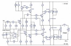
Amplifier is running fine at stable 1.5A bias. Turn on is silent. But a loud transient at turn off. What is causing this? Help please.
Found the problem source, it was the CCS. Put 1Kohm in the base of BD140 and amplifier turn on/off is totally silent. I might put a 1nF from base to collector of BC560 later, but for now let me enjoy some music. Initial impression- The sound is not as good as the BJT version.

Can anybody please tell me how I can decrease the output impedance of the VAS/PhaseSplitter stage? If I am not wrong, the constant current source has higher output impedance than the bootstrap current source which, with BJT outputs, has been the winner to my ears so far. Thanks in advance and please correct me if I am in the wrong track about the current source output impedance.
Attachments
Pleased you have found a solution.
Have you scoped the design for real or just relied on simulation... it looks OK although always good to confirm performance and make sure stability is OK.
In what way would you say the sound was not as good as the Bjt version ?
Does R8 need be that low ? just trying to visualise it all in my head
I'm sure you've probably come across this one of mine on here (not Class A) which uses an emitter follower after your "Q1".
Attachments
Can anybody please tell me how I can decrease the output impedance of the VAS/PhaseSplitter stage? If I am not wrong, the constant current source has higher output impedance than the bootstrap current source which, with BJT outputs, has been the winner to my ears so far. Thanks in advance and please correct me if I am in the wrong track about the current source output impedance.
I don't know. And when shunt regulating my bootstraps, doubly confused.
When a shunt is low impedance, is remaining current of high impedance?
I regulate by no local event, but the sum of nearby output stage currents.
Could a meaningful impedance calculation even exist for this situation?
An active shunt is several fewer components than a constant sink. And
ideally positioned to sample both output stage currents from the center,
with equal weighting of both push and pull. If it is right, does it matter
what is the local impedance? Closure of a global loop drops every node
within to a much lower impedance anyway...
Current in the bootstrap resistor of SRJLH's shunt tail pair is nearly a
dead constant due the shunt, but will vary as needed to cancel power
ripple if any exists. Is that high impedance or low?
Current in the bootstrap resistor of the current steering is anything
but constant. Varies wildy to keep output stage current sum constant,
but allows them freedom to vary in equal but opposite ways. Is that
a low impedance or high, and where exactly do I measure it?
Quadrature feedback for current control is at 90 degrees effect to the
global loop that regulates output voltage. So impedance of this shunt
regulation can't be said to be forced low on account of global closure...
So, what the heck???
Last edited:
In what way would you say the sound was not as good as the Bjt version ?
Does R8 need be that low ? just trying to visualise it all in my head
Of course it will never come close to the real JLH. The R8 is a killer. It will just as good as any quasi-amp.
I'm sure you've probably come across this one of mine on here (not Class A) which uses an emitter follower after your "Q1".
The beta-enhancer is imo part of a good front end in your amp (but it doesn't drive a phase splitter transistor). I wish I would see different output topologies with the same input stage as your amp. If the lateral is replaced with BJT CFP, and if it work, it may be preferable than the P3A.
Hi AndrewT
In my design, non of the vias is working alone. There're always several in parallel to reduce the resistance, and I ask the factory to paste the wall as thick as possible. Of course a copper wire can reduce the resistance, but I don't know how better it will be when the resistance reduced from 0.001Ohm to 0.0001Ohm.
In my design, non of the vias is working alone. There're always several in parallel to reduce the resistance, and I ask the factory to paste the wall as thick as possible. Of course a copper wire can reduce the resistance, but I don't know how better it will be when the resistance reduced from 0.001Ohm to 0.0001Ohm.
- Home
- Amplifiers
- Solid State
- JLH 10 Watt class A amplifier