Nice work! what is the power amplifier in your amp? What's the quiscent current?
Finally built a chassis (sort of) for my JLH.
Still needs some covering up before it's allowed in the house as a permanent feature.
There's still a tiny amount of hum, which I can live with, and sometimes a weird buzzing when a phono input is half plugged in - I suspect to do with a lack of ground connection from the source somehow. Anyway, not an issue really.
Also quite reassured by the fact it weighs 9.3kg.
Hi Siliconray,
Well, I had the caps so thought 'why not'? The transformer and the rectifiers seem happy, so seems to do no harm.
I'm using MJ15003 as my output transistor, and at the moment I'm running at +/- 16.8v with an Iq of about 1.25A. The heatsinks are rather warm, but not hot after an hour, so I will increase Iq one day. At the moment, I'm very happy with it as it is.
Although I will probably increase the feedback capacitance (it's 220uF, I have a couple of 470uF silmics I can use there). I don't want to bypass this cap as others have done, because I'm keen to keep the DC offset as stable, and easy to set, as possible.
And, I may change then input capacitor, but apart from that, I'm very happy with it.
Phil
Power supply Testing
A customer in Australia, Alan, discussed with me about the power supply for JLH amplifier. He send me the circuit of his power supply board, I tried it today and get good result. The circuit is quite simple, just a Darlington capacitor multipler:
This is my testing board
Don't have 2N2955 so replaced with 2SA1215. The 1k resisotor is replaced with 510Ohm to reduce the voltage dropout. The overall current is 3.2A, a small heatsink can keep the transistors from overheating.
The purpose of this circuit is to reduce the 50/60Hz noise. It doesn't really performance like a huge capacitor that can provide power for large dynamic audio signals. A pair of large cap is still necessary for the JLH amp.
A customer in Australia, Alan, discussed with me about the power supply for JLH amplifier. He send me the circuit of his power supply board, I tried it today and get good result. The circuit is quite simple, just a Darlington capacitor multipler:
An externally hosted image should be here but it was not working when we last tested it.
This is my testing board
An externally hosted image should be here but it was not working when we last tested it.
Don't have 2N2955 so replaced with 2SA1215. The 1k resisotor is replaced with 510Ohm to reduce the voltage dropout. The overall current is 3.2A, a small heatsink can keep the transistors from overheating.
The purpose of this circuit is to reduce the 50/60Hz noise. It doesn't really performance like a huge capacitor that can provide power for large dynamic audio signals. A pair of large cap is still necessary for the JLH amp.
Last edited:
Member
Joined 2009
Paid Member
I also feel that it's important to have plenty of capacitance after the capacitance multiplier so that the power supply has a low impedance. Another interesting variation is here: Long Tailed Pair Zen, A W Newby, Jan 2007
Well, the amp has lived in the garage where it was assembled, but last night I had the house to myself and so it made an appearance indoors so I could listen to it properly ")
First of all I noticed there was a lot of hum - that I hadn't heard in the garage. I rebuilt the PSU part in order to get it all in the one chassis, and had cocked up the earthing a bit. I managed to fix it by rearranging the 'star' point for earthing. I have a terminal strip rather than a star, and had the caps' earths closer to the earth to the mains than the signal earth's connection. So the signal return path was sitting on all the charging currents returning from the caps. Whoops!
Anyway, much better now. Obviously, there's still a slight hum, but its much better. Paranoid of hum, I was later annoyed to discover it might have returned, only to realise it was in fact the light in the living room (those low power light bulbs are bloomin' noisy aren't they?!).
Anyway, hum abated, the amp sounded awesome, and very loud! I didn't get to full blast. It was loud enough - and very clear. Bass was surprisingly good. Detail and imaging superb. Absolutely love the amp.
Siliconray, I nearly built a capacitance multiplier, but decided against it in the end. My power rails are already quite low, which I'm happy with, but I didn't want to lower them by a further 4-6V (assuming the cap multiplier drops about 2-3V on both rails). And, I didn't want to lose any dynamics. As you said, the optimum is pure capacitance.
I'm not sure how wise it is to put large capacitance after the capacitance multiplier. I worry that the charging currents are large and have to be through that power transistor. This is probably why you only see a capacitance of about 1000uF after it.
I also noticed, it seemed a little bit sensitive to intereference. I occassionally heard some distortion, a sort of white noise, which was lessened when the CDP was moved further away (I think it was related to the CD servo, it was a periodic click and only really audible when listening on later tracks when it became more frequent).
Unfortunately, my DAC is being rehoused, and not currently functional, so I had to listen to some old bitstream CD player. Even so, this amp just keeps on surprising!
Hi Philpoole
Good to know that you got the amp work! I think there's still room for improving the performance. Better design should be able to reduce the hums further. But I have to say this design is too sensitive to the ripples of supply.
What's the power transistor of your amp? a photo would be great
Good to know that you got the amp work! I think there's still room for improving the performance. Better design should be able to reduce the hums further. But I have to say this design is too sensitive to the ripples of supply.
What's the power transistor of your amp? a photo would be great
Free power PCB for JLH
Hello
Here it is:
Free power PCB for JLH class A amplifier
It's designed by Alan cooker in Australia. We also tested an the result is verey positive.
This donation include not only a blank PCB, but all the components except the transistors.
Thanks and happy listening
Hello
Here it is:
Free power PCB for JLH class A amplifier
It's designed by Alan cooker in Australia. We also tested an the result is verey positive.
This donation include not only a blank PCB, but all the components except the transistors.
Thanks and happy listening
Hello
Here it is:
Free power PCB for JLH class A amplifier
It's designed by Alan cooker in Australia. We also tested an the result is verey positive.
This donation include not only a blank PCB, but all the components except the transistors.
Thanks and happy listening
Is it possible to have two pcb's ?
I am making monoblocks
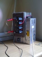
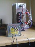
I am running a 30V/11 Amp switch mode power supply followed by 40 000uF caps on the JLH amplifier - it outperforms a 50/60Hz mains transformer based system any time.
Everything about the SMPS just sounds so much less stressed and transparent than with the conventional mains transformer system.
I used a Mean Well S-320-27 adjusted to 30VDC. The power is absolutely stable and noise free.
You guys should try it - throw out the noisy humming 50/60Hz steel and copper and see what a difference it makes.
to have no PSU at all. Yes it will be quiet, i.e. noise free, but there will also be no music.The power is absolutely stable and noise free.
......... throw out the ............. steel and copper and see what a difference it makes.
Make your point, there is no need to exaggerate.
I am running a 30V/11 Amp switch mode power supply followed by 40 000uF caps on the JLH amplifier - it outperforms a 50/60Hz mains transformer based system any time.
Everything about the SMPS just sounds so much less stressed and transparent than with the conventional mains transformer system.
I used a Mean Well S-320-27 adjusted to 30VDC. The power is absolutely stable and noise free.
You guys should try it - throw out the noisy humming 50/60Hz steel and copper and see what a difference it makes.
How exactly did you wire the caps between the SMPS and the JLH amp.?
to have no PSU at all. Yes it will be quiet, i.e. noise free, but there will also be no music.
Make your point, there is no need to exaggerate.
I am not quite sure what you are saying - Have you been drinking from the toilet bowl?
Attachments
- Home
- Amplifiers
- Solid State
- JLH 10 Watt class A amplifier